NOTE!
Unusual measured values on unused phases
▶
If unusual measured values occur on unused phases, bypass the unused cur-
rent transformer inputs.
▶
To do so, for each unused current transformer, connect the terminal marked
with a white dot to the terminal marked with a black dot using a short cable.
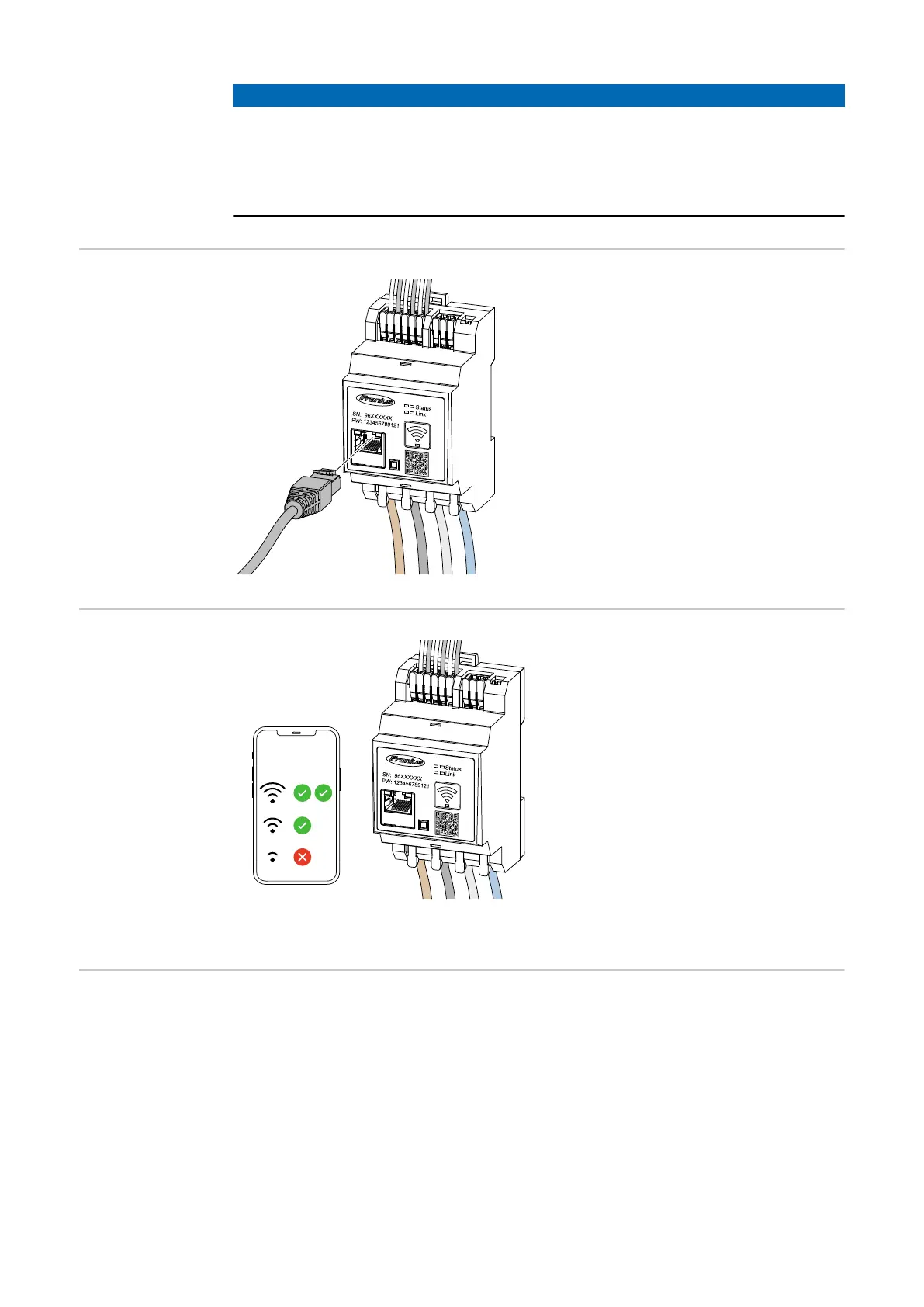
Connecting the
LAN
Observe the following instructions:
-
Use a shielded data cable of type
CAT 5 STP (Shielded Twisted Pair)
or higher.
-
If the data lines are close to the
mains cabling, use cables that are
designed for 300 to 600 V (never
less than the operating voltage).
-
Use double-insulated or sheathed
data cables when they are close to
bare conductors.
-
The use of a static IP address is
recommended.
WLAN configur-
ation
IMPORTANT!
Ensure sufficient WLAN signal
strength at the installation site. If the
signal strength is low, a WLAN booster
must be installed, for example.
The use of a static IP address is re-
commended.
Connecting the
Modbus RTU
Connect the data communication connections of the Fronius Smart Meter IP to
the Modbus interface of the Fronius inverter using a CAT 5 STP (Shielded Twis-
ted Pair) or higher data cable.
The Fronius Smart Meter IP can also be connected to the network (LAN /
WLAN). This allows software updates to be carried out.
Standard Modbus address & TCP port:
-
Address: 1
-
TCP port: 502
23