4-1
Section 4 Software Interface
4-1 Analog Input Module
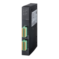
NP1AXH8V-MR (voltage input module) and NP1AXH8I-MR (current input module) occupy 12 words of I/O area (input: 8 words,
output: 4 words).
4-1-1 Memory allocation in Switch Batch Setting mode
Moving average execution times for conversion operation is set with the “Average” switch (upper side switch on the module
rear panel), and operation range is set with the “Range” switch (lower side switch on the module rear panel).
<Status list>
Status code Error Descrip tion
30002
(7532h)
EEPROM calibration data
error (Module fatal fault)
If the cali bration data of EEPROM i s destroyed or if EEPROM cannot be
written or read, this error is notified. Module internal EEPROM is abnormal.
If thi s error occurred, it is necessary to replace the module.
30003
(7533h)
EEPROM user setting data
error
If the user setting data of EEPROM is destroyed, this error is noti fied.
If thi s error occurred, all parameters need to be reset. If thi s error recurs
even after parameters are reset, the module seems to have failed.
30004
(7534h)
Internal power supply down
If the internal power supply of the module becomes down, this error is
notified.
30005
(7535h)
Switch setting erro r
If the operati on setting switch on the module rear panel is set at i nvalid
position, this error is notified.
30006
(7536h)
Conversion error
If conversion became abnormal because the module failed or was used in an
out-of-spec environment, this error is notified.
This module to CPU module
CPU module to this module
Offset
address
15(F)
+0
+1
+2
+3
+4
+5
+6
+7
+8
+9
+10
+11
Channel1 Digitaloutputvalue/Status
Channel 2 Digital output value / Status
Channel 3 Digital output value / Status
Channel4 Digitaloutputvalue/Status
Channel 5 Digital output value / Status
Channel 6 Digital output value / Status
Channel 7 Digital output value / Status
Channel 8 Digital output value / Status
Unused (fixed to 0 (zero))
Unused (fixed to 0 (zero))
Unused (fixed to 0 (zero))
Unused (fixed to 0 (zero))
0
Ordinarily digital output values (INT type) are stored in the registers explained above. If the module becomes
abnormal, the following status code (INT type) is stored in these registers. When making an application program,
be sure to interlock erroneous and normal (A/D conversion) conditions.

 Loading...
