EasyManua.ls Logo

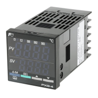
Fuji Electric Model: PXR4 User Manual

Fuji Electric Model: PXR4
32 pages
To Next Page IconTo Next Page
Page #1 background imageLoading...
Page #1 background image
– 1 –
Thank you for your purchasing "Fuji Digital Temperature Controller."Please check that the product is exactly the
one you ordered and use it according to the following instructions. (Please refer to a separate operation manual
for details.) Dealers are cordially requested to ensure the delivery of this Instruction Manual to hands of the end-
users.
NOTICE The contents of this document may be changed in the future without prior notice.
We paid the utmost care for the accuracy of the contents. However, we are not liable for direct and
indirect damages resulting from incorrect descriptions, omission of information, and use of informa-
tion in this document.
Read before using ................................................ 3
Index ................................................................ 7
1. Installation/mounting ...................................... 8
2. Wiring ............................................................. 9
3. Usage............................................................. 10
4. Display and operation .................................... 11
5. Setting methods of temperature and
paramenters............................................ 12
1st block parameter........................................ 12
2nd block parameter ...................................... 13
3rd block parameter ....................................... 14
6. Function ......................................................... 15
6-1 ON/OFF control ...................................... 15
6-2 Auto-tuning (AT) ...................................... 16
6-3 Self-tuning............................................... 17
6-4 Alarm function [option] ............................ 19
6-5 Ramp/soak function [option] ................... 21
6-6 Communication function [option]............. 22
6-7 Digital input (DI function) [option]............ 23
6-8 Other functions ....................................... 24
7. Setting of input type and control algorithm..... 25
8. Error indications ............................................. 27
[Table1] Input type code ....................................... 28
[Table2] Control output action code...................... 28
[Table3] Input range (Standard range) ................. 29
[Table4] Alarm action type code ........................... 30
PXR Model Code Configuration ........................... 31
Specification......................................................... 32
CONENTS
Instruction Manual
Micro-controller X
Model: PXR4
INP-TN1PXRa-E
Fuji Electric Co., Ltd.
Head Office
11-2, Osaki 1-chome, Shinagawa-ku, Tokyo, 141-0032 Japan
http://www.fujielectric.co.jp
Fuji Electric Instruments Co., Ltd.
Sales Div. International Sales Dept.
No.1, Fuji-machi, Hino-city, Tokyo, 191-8502 Japan
Phone : +81-42-585-6201,6202
Fax : +81-42-585-6187,6189
http://www.fic-net.co.jp
Question and Answer IconNeed help?

Do you have a question about the Fuji Electric Model: PXR4 and is the answer not in the manual?

Fuji Electric Model: PXR4 Specifications

Power IconPower
power voltage100 (- 15%) to 240V AC (+10%)
power consumption15V AC or less/240V AC
maximum current20mA or less
Outputs IconOutputs
relay contact output 1SPDT contact, 220VAC / 30VDC 3A
relay contact output 2SPST contact, 220VAC / 30VDC 3A
alarm outputRelay contact (SPST contact) 220V AC / 30V DC 1A
Operating Environment IconOperating Environment
ambient temperature-10 to 50°C
operating ambient humidity90%RH or less
preservation temperature-20 to 60°C

Summary

Installation and Mounting

Outline and Panel Cutout Dimensions

Technical drawings and dimensions for unit installation and panel cutouts.

Cautions on Wiring

Important safety notes and best practices for wiring the controller.

Side-by-Side Installation Note

Guidelines for installing multiple units adjacent to each other, including thermal considerations.

Wiring

Terminal Connection Diagram

Detailed diagram showing terminal connections for power, signals, and outputs.

Wiring Notes

Explanations for specific terminal connections and accessory installations.

Usage and Operation

Functional Parts and Functions

Overview of the controller's buttons, displays, and indicator lamps.

Setting Keys Functionality

Description of how each setting key (S1, S2, S3) operates.

Display and Operation Modes

Standby Mode Operation

How the controller behaves and what is displayed in standby mode.

Operation Mode Usage

Procedures for changing set values and navigating between parameter blocks.

Parameter Setting Mode

Step-by-step guide for selecting and changing parameter values.

Parameter Setting Methods

1st Block Parameters

Detailed list and description of parameters in the first block, including standby, alarm, and auto-tuning settings.

2nd Block Parameters

Comprehensive list of parameters related to PID control, input, and range settings.

3rd Block Parameters

Parameters for control action, alarm functions, digital input, and communication settings.

Functions

ON/OFF Control Mode

Explanation and examples of the ON/OFF control mode operation.

Auto-tuning and Self-tuning

Guides for automatic and self-tuning to optimize PID parameters.

Optional Functions

Details on alarm, ramp/soak, communication, and digital input functions.

Other Functions

Details on parameters like bAL and Ar for overshoot suppression.

Input Type and Control Algorithm

Setting the Input Type

How to select the correct sensor type and check input configurations.

Setting the Control Algorithm

Guide to selecting ON/OFF, PID, or Fuzzy control algorithms.

Error Indications

Error Code Descriptions

List of error codes, their possible causes, and control output behavior.

Reference Tables

Input Type Codes

Codes for various sensor input types like Thermocouple, RTD, and voltage/current signals.

Control Output Action Codes

Codes defining heating/cooling control actions and outputs at burn-out.

Input Range Standards

Standard temperature and signal ranges for different input types.

Alarm Action Type Codes

Detailed codes for alarm types, action logic, and dual set value configurations.

Model Code Configuration

Digit Specifications

Breakdown of model code digits and their corresponding specifications.

Specifications

Electrical Specifications

Details on power voltage, consumption, output ratings, and communication interface.

Environmental and Input Specs

Ambient conditions, humidity, preservation temperature, and digital input capacity.

Related product manuals