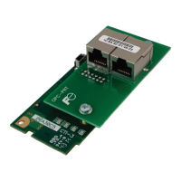
9.5.5 PROFIdrive Profile
For optimal interoperability, the interface card supports the PROFIdrive profile version 4.1. Use of the
PROFIdrive profile is optional and is not recommended unless specifically required in the PROFINET
system specification. No explicit configuration of the interface card is necessary in the studio when using
the PROFIdrive profile. The controller must support the PROFIdrive profile and must be c onfigured to
use the “Standard Telegram 1” module on the interface card. If the controller does not support the
PROFIdrive profile, use the configurable I/O “IN: 32 WORDS, OUT: 32 WORDS” module. The
PROFIdrive profile is only partially described in this manual due to its complexity. The c omplete
PROFIdrive profile specifications can be obtained from http://www.profibus.com/
.
Some other notes of interest include:
• Implements Application Class 1 (standard drive)
• Supports only Standard Telegram 1 (ST1, PZD-2/2) on slot 1 (similar to Profibus PPO type 3)
• Supports only Speed Control Mode
9.5.5.1 PROFIdrive Standard Telegram 1
The standard telegram 1 mapping is described in Table 38.
Table 38: Standard Telegram 1
IO Data
Word
Offset
Setpoint (PLC to Inverter) Actual Value (Inverter to PLC)
Significance Description Significance Description
1 NSOLL_A
NIST_A Speed actual
9.5.5.2 PROFIdrive Control and Status Words
The control word, STW1, is the principal means for controlling the drive. It is sent by the controller (PLC)
to the device (inverter). The bitmapping for the control word is described in Table 39. The status word,
ZSW1, returns status information from the inverter to the controller. The bitmapping for the status word
is described in Table 40.
Table 39: STW1 Control Word Mapping
Bit Value Significance Description
0
1
2
3
Enable inverter operation
Disable inverter operation
4
Enable the ramp frequency generator (RFG)
Hold the output frequency to 0 Hz
5
0 Freeze Ramp Generator
Freeze the RFG with the current output
frequency
6
7
1 Fault Acknowledge
Reset the alarm on a pos itive edge (0→1
transition)
10
1 Control By PLC
Enable remote c ontrol. The IO process data
is valid.
0 No Control By PLC
Disable remote control. The IO process data
is not valid.
Run in the reverse direction

 Loading...