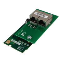
9.5 PROFINET IO
9.5.1 Overview
The PROFINET IO device driver allows a controller to interact with the interface card via cyclic data
exchange and acyclic read/write requests. The I/O data is entirely user-configurable, and is utilized when
a standard I/O module is chosen during network configuration.
Some other notes of interest are:
• Allows simultaneous access to only 1 PROFINET controller.
• Supports conformanc e class B and real time (RT) communication.
• Supports the highest Netload Class III.
• Supports MRP (Media Redundancy Protocol) client.
• Supports DCP (Discovery Control Protoc ol).
• Supports alarms.
• Supports I&M.
• The lowest supported I/O Cycle Update Time (in STEP 7 or an equivalent hardware configuration
tool) is 1ms.
• The GSDML file can be obtained from the included CD-ROM or downloaded from
product web
page on the internet.
• Supports several user-configurable I/O modules with up to 32 input words and 32 output words.
• Supports the PROFIdrive profile version 4.1.
• No explicit module selection is required on the interface card: the module will be selected
automatic ally according to the controller’s configuration.
• If a timeout occurs on the RT connection, the driver can be configured to trigger a timeout event as
described in section 5.4.1. The timeout value is dictated by the PROFINET controller and is at
least three times the IO Cycle update time. The timeout value is also known as the “IO Cycle
Watchdog” time.
9.5.2 Device Settings
In the studio’s Project panel, navigate to OPC-PRT…Ethernet…PROFINET IO.
Device Name
The device name / station name must be unique across the entire PROFINET network, because it is
used by controllers to uniquely identify PROFINET devices. This string must conform to the device name
requirements contained in the PROFINET specification.
9.5.3 Connection Timeout Options
In the studio’s Project panel, navigate to OPC-PRT…Ethernet…PROFINET IO. The following
configuration options will determine the actions to be taken by the card if the PROFINET IO connection
is abnormally terminated or lost.
Timeout Action
Select an action from the drop down menu:
“None” ..................................No effect. The inverter will continue to operate with the last available
settings.
“Apply Fail-safe Values” .......Apply the fail-safe values as described in section 5.4.1.
“Fault Drive” .........................The behavior will depend on the timeout conditions set by the inverter
(function codes o27 and o28), which may result in an Er5 fault. Refer to
section 3.2.
Enable Drive Fault Reset
This will clear the Er5 fault once communication is re-established. This option is only available if the
Timeout Action is set to “Fault Drive”.
9.5.4 Cyclic I/O Produced and Consumed Data Access Settings
In the studio’s Project panel, add OPC-PRT…Ethernet…PROFINET IO…Produced Data Word and/or
Consumed Data Word.

 Loading...