99
FMPC
2
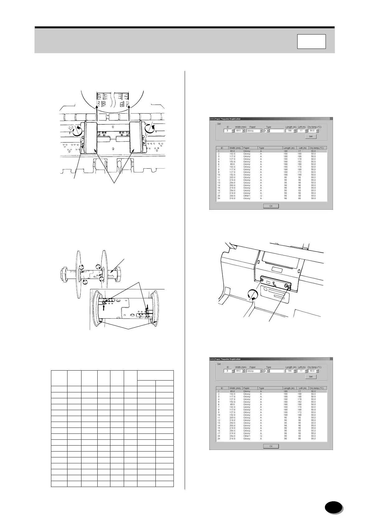
Remove the two screws and adjust the paper
guide width in accordance with the paper width.
N
TE:
Do not loosen the red painted screws.
3
Remove the two screws and adjust the flange
width in accordance with the paper width.
4
Select a paper ID referring to the table below,
and enter the data.
N
TE:
To register paper not listed in the table, use a fresh
magazine ID not used.
5
Click [Set].
6
Install the ID chip on the paper magazine with
the two screws.
7
Click [OK]
• Operation returns to the “4 Setup and
Maintenance” screen.
Paper Guide
Screws (2)
EZ854
Paper Shaft
Screws (2)
Flange
EZ855
189Glossy A 180 180 55.0 62.0
2 102 Glossy A 180 180 55.0 62.0
3 117 Glossy A 180 180 55.0 62.0
4 127 Glossy A 180 180 55.0 62.0
5 152 Glossy A 180 180 55.0 62.0
689Glossy A 180 180 55.0 62.0
7 102 Glossy A 180 180 55.0 62.0
8 117 Glossy A 180 180 55.0 62.0
9 127 Glossy A 180 180 55.0 62.0
10 152 Glossy A 180 180 55.0 62.0
11 203 Glossy A 90 90 55.0 67.0
12 210 Glossy A 90 90 55.0 67.0
13 254 Glossy A 90 90 55.0 67.0
14 203 Glossy A 90 90 55.0 67.0
15 152 Glossy A 180 180 55.0 62.0
16 254 Glossy A 90 90 55.0 67.0
18 254 Glossy A 90 90 55.0 67.0
Magazine
ID
Paper
Paper
Width
(mm)
Paper
Length
(m)
Left
Length
(m)
Type
DryingTemp.(°C)
LP1500SC LP2000SC
Screws (2)
EZ1218
distributed by www.minilablaser.com



 To Next Page