The wiring procedure for the FVR0.75AS1S-4
is given below as an example. For other inverter
types, perform wiring in accordance with their individual terminal arrangement.
①
Grounding terminal ( G)
Be sure to ground either of the two grounding terminals for safety and noise reduction. It is
stipulated by the Electric Facility Technical Standard that all metal frames of electrical
equipment must be grounded to avoid electric shock, fire and other disasters.
Grounding terminals should be grounded as follows:
1) Ground the inverter in compliance with the national or local electric code.
2) Connect a thick grounding wire with a large surface area. Keep the wiring length as short
as possible.
②
Inverter output terminals, U, V, W and grounding terminal ( G)
1) Connect the three wires of the three-phase motor to terminals U, V, and W, aligning phases
each other.
2) Connect the grounding wire of terminals U, V, and W to the grounding terminal ( G).
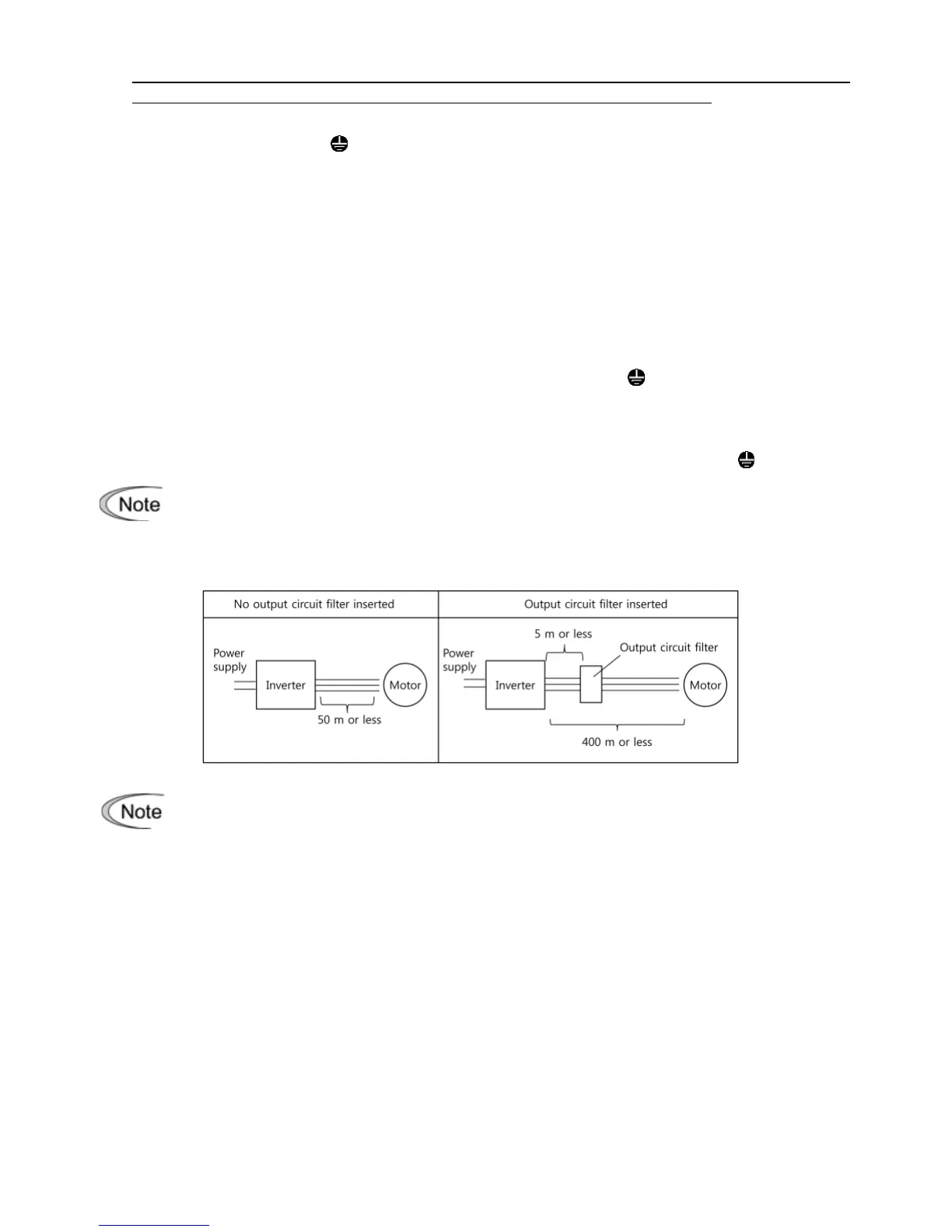
- The wiring length between the inverter and motor should not exceed 50 m. If it exceeds
50 m, it is recommended that an output circuit filter (option) be inserted.
- Do not use one multicore cable to connect several inverters with motors.
• Do not connect a phase-advancing capacitor or surge absorber to the inverter’s
output lines (secondary circuit).
• If the wiring length is long, the stray capacitance between the wires will increase,
resulting in an outflow of the leakage current. It will activate the overcurrent
protection, increase the leakage current, or will not assure the accuracy of the
current display. In the worst case, the inverter could be damaged.