Chapter 3 OPERATION USING THE KEYPAD
3.1 Names and Functions of Keypad Components
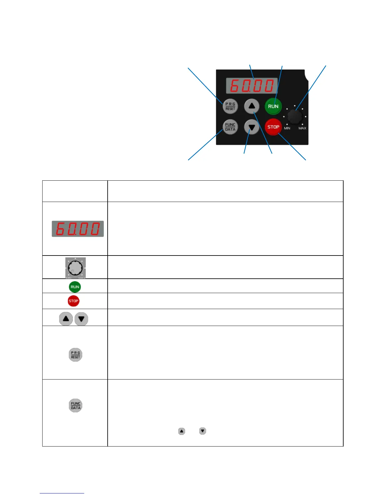
7-segment
As shown in the figure at right, the
keypad consists of a four-digit
7-segment LED monitor, a potenti-
ometer (POT), and six keys.
The keypad allows you to start and
stop the motor, monitor running
status, configure the function code
data, check I/O signal states, and
display maintenance information and
alarm information.
Program/Reset
key
LED monitor
RUNkey Potentiometer
Function/Data key Down key Up key STOP key
Table 3.1 Names and Functions of Keypad Components
Four-digit, 7-segment LED monitor which displays the following according to the
operation modes *.
In Running mode: Running status information (e.g., output frequency,
current, and
voltage)
In Programming mode: Menus, function codes and their data
In Alarm mode: Alarm code which identifies the error factor if the
protective function is activated.
Potentiometer (POT) which is used to manually set a reference frequency,
auxiliary frequencies 1 and 2 or PID process command.
RUN key. Press this key to run the motor.
STOP key. Press this key to stop the motor.
UP/DOWN keys. Press these keys to select the setting items and change the
function code data displayed on the LED monitor.
Program/Reset key which switches the operation modes* of the inverter.
In Running mode: Pressing this key switches the inverter to Programming
mode.
In Programming mode: Pressing this key switches the inverter to Running
mode.
In Alarm mode: Pressing this key after removing the error factor
switches the inverter to Running mode.
Function/Data
key which switches the operation you want to do in each mode as
follows:
In Running mode: Pressing this key switches the information to be displayed
concerning the status of the inverter (output frequency, output current, output
voltage, etc.).
In Programming
mode:
Pressing this key displays the function codes and sets their
data entered with the and keys or the
POT.
In Alarm mode: Pressing this key displays detailed alarm information.
* FVR-Micro features three operation modes: Running, Programming, and Alarm. Refer to Section 3.2
"Overview of Operation Modes."