Functions
Analog
input
[13]
Power
supply
for
potenti-
ometer
Power supply (+10 VDC) for an external frequency command potentiometer
(Potentiometer: 1 to 5
k
Ω
)
A potentiometer of 1/2 W rating or more should be connected
Allowable maximum output current: 10mA.
[12]
Analog
setting
voltage
input
(1) The frequency is commanded according to the external analog input voltage.
0 to +10 (VDC)/0 to 100 (%) (Normal operation)
+10 to 0 (VDC)/0 to 100 (%) (Inverse operation)
(2) Used for reference signal (PID process command) or PID feedback signal.
(3) Used as additional auxiliary setting for various main frequency commands.
* Input impedance: 22
k
Ω
* The allowable maximum input is +15 VDC; however, the voltage higher than
+10 VDC is treated as +10 VDC.
[C1]
Current
input
(1) The frequency is commanded according to the external analog input current.
+4 to +20 mA DC/0 to 100% (Normal operation)
+20 to +4 mA DC/0 to 100% (Inverse operation)
+0 to +20 mA DC/0 to 100% (Normal operation)
+20 to 0 mA DC/0 to 100% (Inverse operation)
(2) Used for reference signal (PID process command) or PID feedback signal.
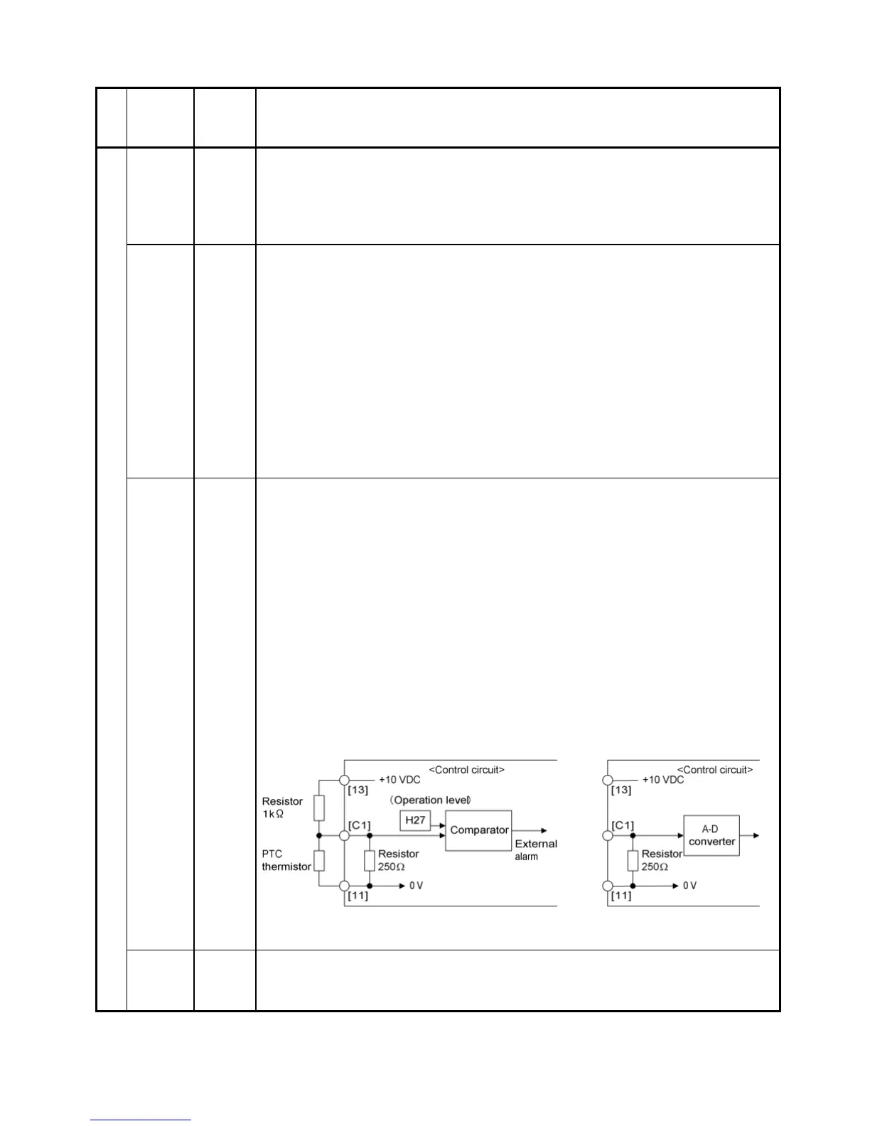
(3) Connects PTC (Positive Temperature Coefficient) thermistor for motor
protection.
(4) Used as additional auxiliary setting for various main frequency commands.
* Input impedance:
250
Ω
* The allowable maximum input is +30 mA DC; however, the current larger
than +20 mA DC is treated as +20 mA DC.