Table 2.7 Symbols, Names and Functions of the Control Circuit Terminals (Continued)
Functions
Transistor o
utput
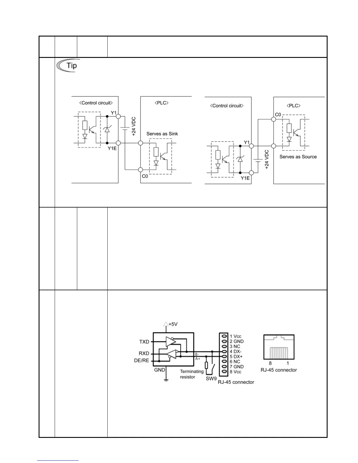
Connecting programmable controller (PLC) to terminal [Y1]
Figure 2.9 shows two examples of circuit connection between the transistor output of the
inverter’s control circuit and a PLC. In example (a), the input circuit of the PLC serves as a
sink for the control circuit, whereas in example (b), it serves as a source for the control circuit.
(a) PLC serving as sink (b) PLC serving as
source
Figure 2.9 Connecting PLC to Control
Circuit
Relay contact output
[30A]
,
[30B]
,
[30C]
Alarm
relay
output
(for any
fault)
(1) Outputs a contact signal (SPDT) when a protective function has been
activated to stop the motor.
Contact rating: 250 VAC 0.3A cos φ = 0.3
+48 VDC, 0.5A
(2) A command similar to terminal [Y1] can be selected for the transistor output
signal and use it for signal output.
(3) Switching of the normal/negative logic output is applicable to the fol
two contact outputs: "Terminals [30A] and [30C] are short-circuited
for ON signal output" or "Terminals [30B] and [30C] are short-circuited (non-
excite) for OFF signal output."
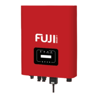
communication
RJ-45 connector
(RS-485)
(1) Used to connect an optional keypad to the inverter.
(2) Used to connect the inverter to a computer running Loader via the RS-485
communications link. (For the terminating resistor, refer to Section 2.3.7.)
Figure 2.10 RJ-45 Connector and its Pin Assignment
*Pins 1, 2, 7 and 8 are exclusively assigned to power lines for an optional
keypad. When connecting any other device to the RJ-45 connector, do not use
those pins.
For the location of the RJ-45 connector, refer to Figure 2.11 "Locations of Jumper
Switches and RJ-45 Connector."