Check Point 2 : Remove connector and check Thermistor resistance value
Check Point 1 : Check connection of Connector
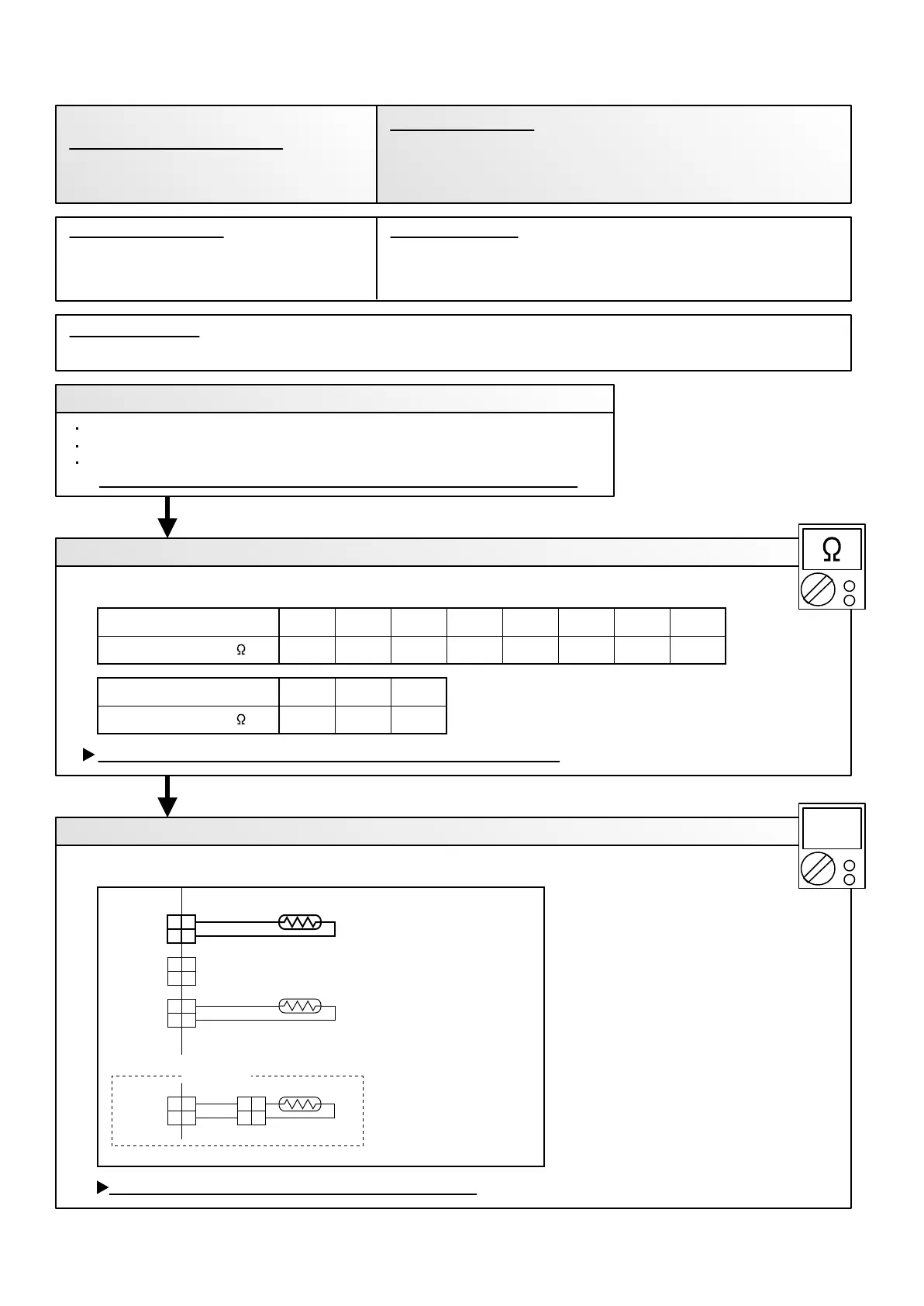
Check Point 3 : Check voltage of Controller PCB (DC5.0V)
6.51
35
8.04
30
10.012.515.820.225.933.6
2520151050Temperature (°C )
OK
OK
Resistance Value (k )
3.594.355.30
504540
THERMISTOR
(PIPE TEMP.)
THERMISTOR
(ROOM TEMP.)
1. Connector connection failure 2.Thermistor failure 3. Controller PCB failure
Check if connector is removed.
Check erroneous connection.
Check if thermistor cable is open.
>> Upon correcting the removed connector or mis-wiring, reset the power.
Thermistor Characteristics (Approx. value)
If Thermistor is either open or shorted, replace it and reset the power.
Make sure circuit diagram of indoor unit and check terminal voltage at Thermistor (DC5.0V)
If the voltage does not appear, replace Controller PCB.
02-07
Temperature (°C )
Resistance Value (k )
Indoor Unit Controller PCB Circuit
Room Temperature Thermistor
When Room Temperature Thermistor open or short-circuit is
detected at power ON.
Trouble shooting 3
INDOOR UNIT Error Method:
Indicate or Display:
Refer to error code table.
Room Temperature Sensor Error
1
2
1
2
1
2
1
2
1
2
1
2
Cable color
AR : GRAY
AU : BLACK
Cable color
AB, AR : BLACK
AU : RED
AB Type
CN 7
CN 5
CN 8
1
2
1
2
1
2
1
2
BLACK GRAY
CN 5
DC
Detective Actuators: Detective details:
Forecast of Cause:
 Loading...