OK
OK
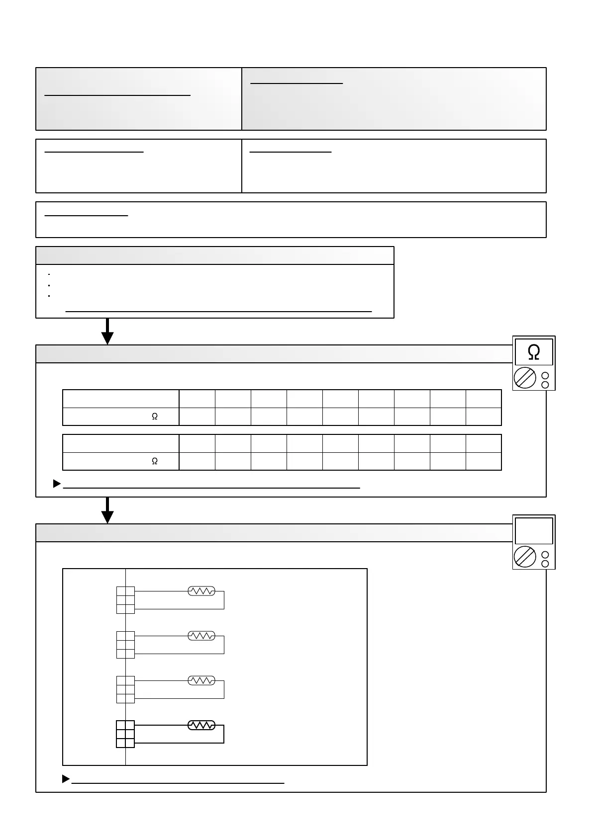
THERMISTOR
( DISCHARGE PIPE )
THERMISTOR
( COMPRESSOR TEMP. )
THERMISTOR
( HEAT EXCHANGER )
THERMISTOR
( OUTDOOR TEMP. )
BLACK
BROWN
BLUE
BROWN
1. Connector connection failure 2.Thermistor failure 3. Main PCB failure
Check Point 1 : Check connection of Connector
Check if connector is removed.
Check erroneous connection.
Check if thermistor cable is open.
>> Upon correcting the removed connector or mis-wiring, reset the power.
Check Point 2 : Remove connector and check Thermistor resistance value
Thermistor Characteristics (Approx. value)
If Thermistor is either open or shorted, replace it and reset the power.
Check Point 3 : Check voltage of Main PCB (DC5.0V)
Make sure circuit diagram of outdoor unit and check terminal voltage at Thermistor (DC5.0V)
If the voltage does not appear, replace Main PCB.
02-09
4.77
25
5.98
20
7.569.6312.416.121.027.8
151050-5-10Temperature (°C )
Resistance Value (k )
2.082.533.11
454035Temperature (°C )
Resistance Value (k )
3.84
30
1.71
50
1.19
60
0.84
70
0.60
80
0.45
90
0.33
100
Outdoor Unit Main PCB Circuit
Heat Exchanger Temperature
Thermistor (Outlet)
When Heat Exchanger Temperature Thermistor (Outlet) open or
short-circuit is detected at power ON or while running the compressor.
Trouble shooting 5
OUTDOOR UNIT Error Method:
Indicate or Display:
Refer to error code table.
Outdoor Heat Exchanger Temperature
Sensor (Outlet) Error
1
2
3
1
2
3
1
2
3
1
2
3
1
2
3
1
2
3
1
2
3
1
2
3
CN 64
CN 62
CN 63
CN 65
BROWN
BLUE
BROWN
BLACK
DC
Detective Actuators: Detective details:
Forecast of Cause:
 Loading...