OK
OK
1. Connector connection failure 2. Thermistor failure 3. Main PCB failure
Check Point 1 : Check connection of Connector
Check if connector is removed.
Check erroneous connection.
Check if thermistor cable is open.
>> Upon correcting the removed connector or mis-wiring, reset the power.
Check Point 2 : Remove connector and check Thermistor resistance value
Thermistor Characteristics (Rough value)
If Thermistor is either open or shorted, replace it and reset the power.
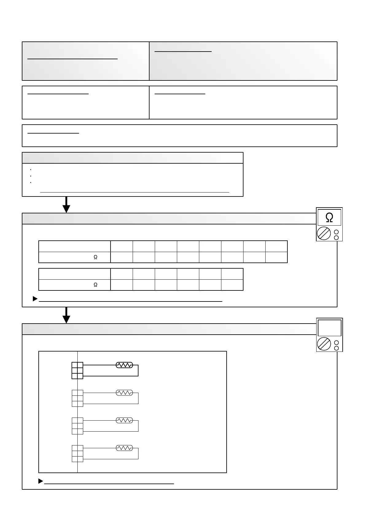
Check Point 3 : Check voltage of Main PCB (DC5.0V)
Make sure circuit diagram of outdoor unit and check terminal voltage at Thermistor (DC5.0V)
If the voltage does not appear, replace Main PCB.
02-17
17.8
50
26.3
40
40.062.679.1101130169
3020151050Temperature (°C )
Resistance Value (k )
6.278.7012.3
807060Temperature (°C )
Resistance Value (k ) 4.60
90
3.43
100
2.00
120
Outdoor Unit Main PCB Circuit
Compressor Temperature Thermistor
When Compressor Temperature Thermistor open or short-circuit is
detected at power ON or while running the compressor.
Trouble shooting 13
OUTDOOR UNIT Error Method:
Indicate or Display:
Refer to error code table.
Compressor Temperature Sensor Error
THERMISTOR
( DISCHARGE PIPE )
THERMISTOR
( COMPRESSOR TEMP. )
THERMISTOR
( HEAT EXCHANGER )
THERMISTOR
( OUTDOOR TEMP. )
BLACK
BROWN
BLUE
BROWN
1
2
3
1
2
3
1
2
3
1
2
3
1
2
3
1
2
3
1
2
3
1
2
3
CN 64
CN 62
CN 63
CN 65
BROWN
BLUE
BROWN
BLACK
DC
Detective Actuators: Detective details:
Forecast of Cause:
 Loading...