OK
OK
1. Connector connection failure 2.Thermistor failure 3. Controller PCB failure
Check Point 1 : Check connection of Connector
Check if connector is removed.
Check erroneous connection.
Check if thermistor cable is open.
>> Upon correcting the removed connector or mis-wiring, reset the power.
Check Point 2 : Remove connector and check Thermistor resistance value
Thermistor Characteristics (Approx. value)
If Thermistor is either open or shorted, replace it and reset the power.
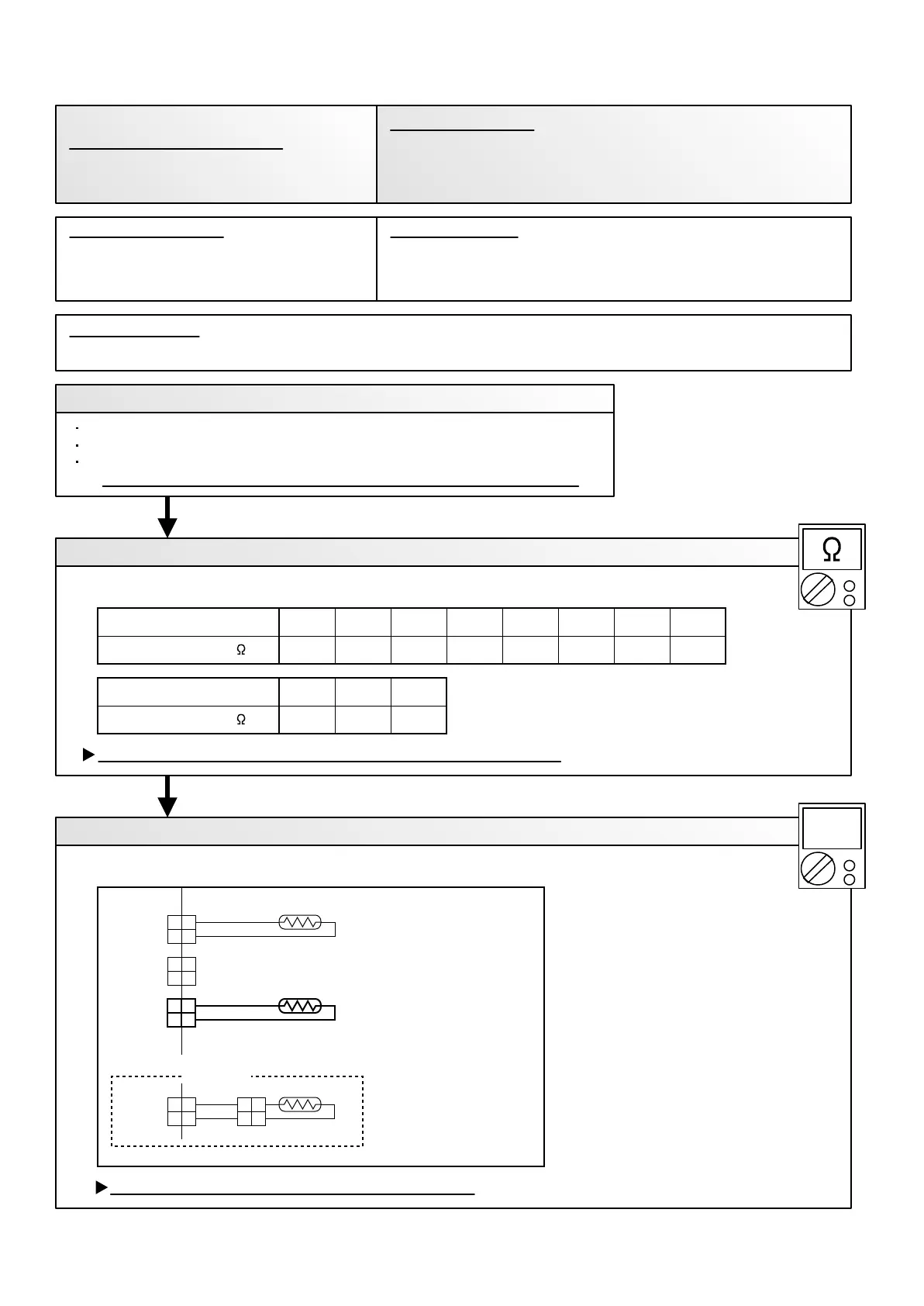
Check Point 3 : Check voltage of Controller PCB (DC5.0V)
Make sure circuit diagram of indoor unit and check terminal voltage at Thermistor (DC5.0V)
If the voltage does not appear, replace Controller PCB.
02-08
31.7
35
39.6
30
49.762.980.3103134176
2520151050Temperature (°C )
Resistance Value (k )
17.120.825.6
504540Temperature (°C )
Resistance Value (k )
Indoor Unit Controller PCB Circuit
Heat Exchanger Temperature Thermistor
When Heat Exchanger Temperature Thermistor open or short-circuit is
detected at power ON.
Trouble shooting 4
INDOOR UNIT Error Method:
Indicate or Display:
Refer to error code table.
Indoor Heat Exchanger Temperature
Sensor Error
THERMISTOR
(PIPE TEMP.)
THERMISTOR
(ROOM TEMP.)
1
2
1
2
1
2
1
2
1
2
1
2
Cable color
AR : GRAY
AU : BLACK
Cable color
AB, AR : BLACK
AU : RED
CN 7
CN 5
CN 8
AB Type
1
2
1
2
1
2
1
2
BLACK GRAY
CN 5
DC
Detective Actuators: Detective details:
Forecast of Cause:
 Loading...