En-11
CAUTION
•Topeelthelmfromtheleadcable,useadedicatedtool
that will not damage the conductor cable.
•Wheninstallingascrewontheterminalblock,donotcut
the cable by overtightening the screw. On the other hand,
an undertightened screw can cause faulty contact, which
will lead to a communication failure.
]1
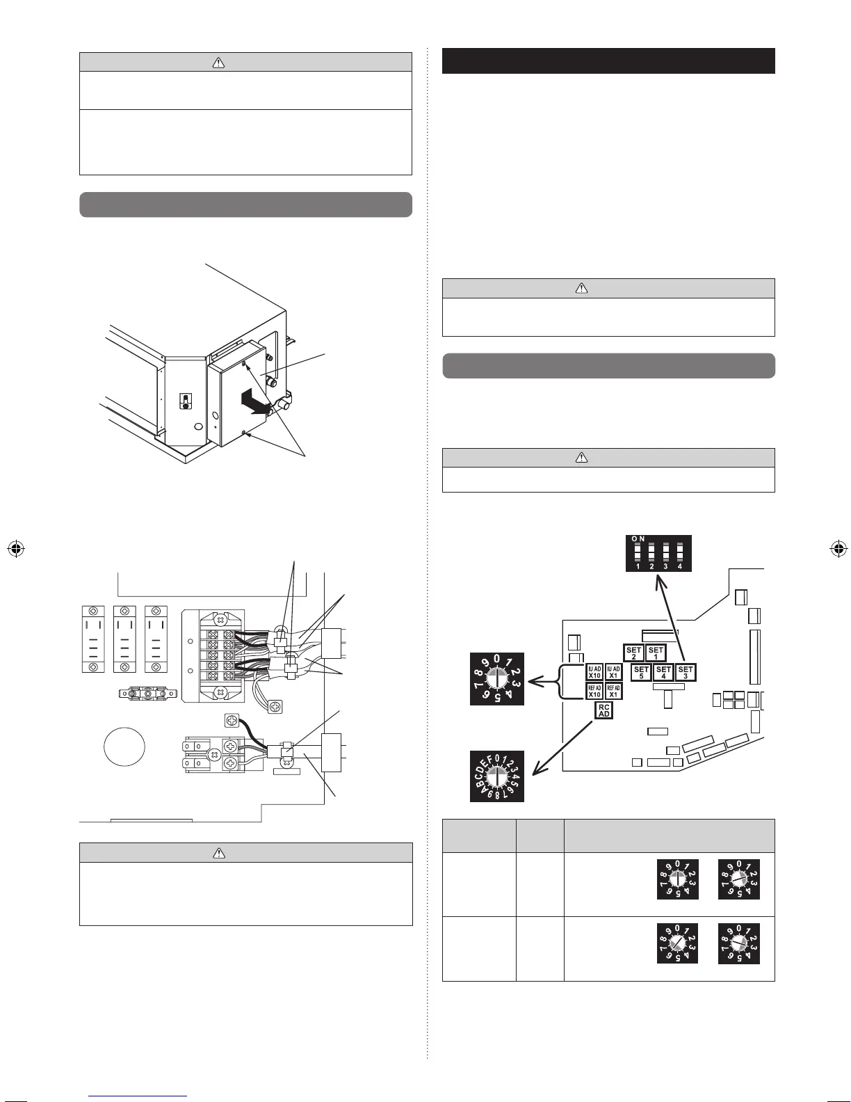
6.4. Connection of wiring
(1) Removethecontrolboxcoverandinstalleachconnection
cable.
Loosen the screws.
(2 locations)
Coverbox
(2) After wiring is complete, clamp the remote control cable,
transmission cable and power supply cable with binder.
Remote
control cable
Y1:Red
Y2:White
Y3:Black
Binder (Medium)
(Accessories)
L,N:Power
supply cable
X1,X2:
Transmission
cable
Binder
(Medium)
(Accessories)
CAUTION
•Wheninstallingascrewontheterminalblock,donotcut
the cable by overtightening the screw. On the other hand,
an undertightened screw can cause faulty contact, which
will lead to a communication failure.
(3) Attachthecontrolboxcover.
7. FIELD SETTING
• RefertothefollowingthreeitemsforsettingtheFIELD
SETTING address. The respective settings are included
below.
(1)
IUAD,REFADSWsettings
... This section
(2) Remote control settings ........ Refer to the wired or
wireless remote control
manual for detailed setting
information.(SetIUAD,
REFADSWto0)
(3) Automatic address settings ... Refer to the indoor unit
manual for detailed setting
information.(SetIUAD,
REFADSWto0)
CAUTION
•Be sure to turn OFF the power before performing the
eldsetting.
]1
7.1. Setting the address
Manual address setting method
• Theindoorunitaddressandtherefrigerantcircuitaddress
can also be set up through the wireless remote controller
CAUTION
•Useaninsulatedscrewdrivertosetthedipswitches.
Rotary switch
Example:“0”
Rotary switch
Example:“0”
Dipswitch
“SET3”
SW
1
SW
2
SW
3
SW
4
Setting
Setting
range
Type of switch
Indoor unit
address
0–63
Setting
example
2
IUAD×10 IUAD×1
Refrigerant
circuit
address
0–99
Setting
example
63
REFAD×10
REFAD×1