En-12
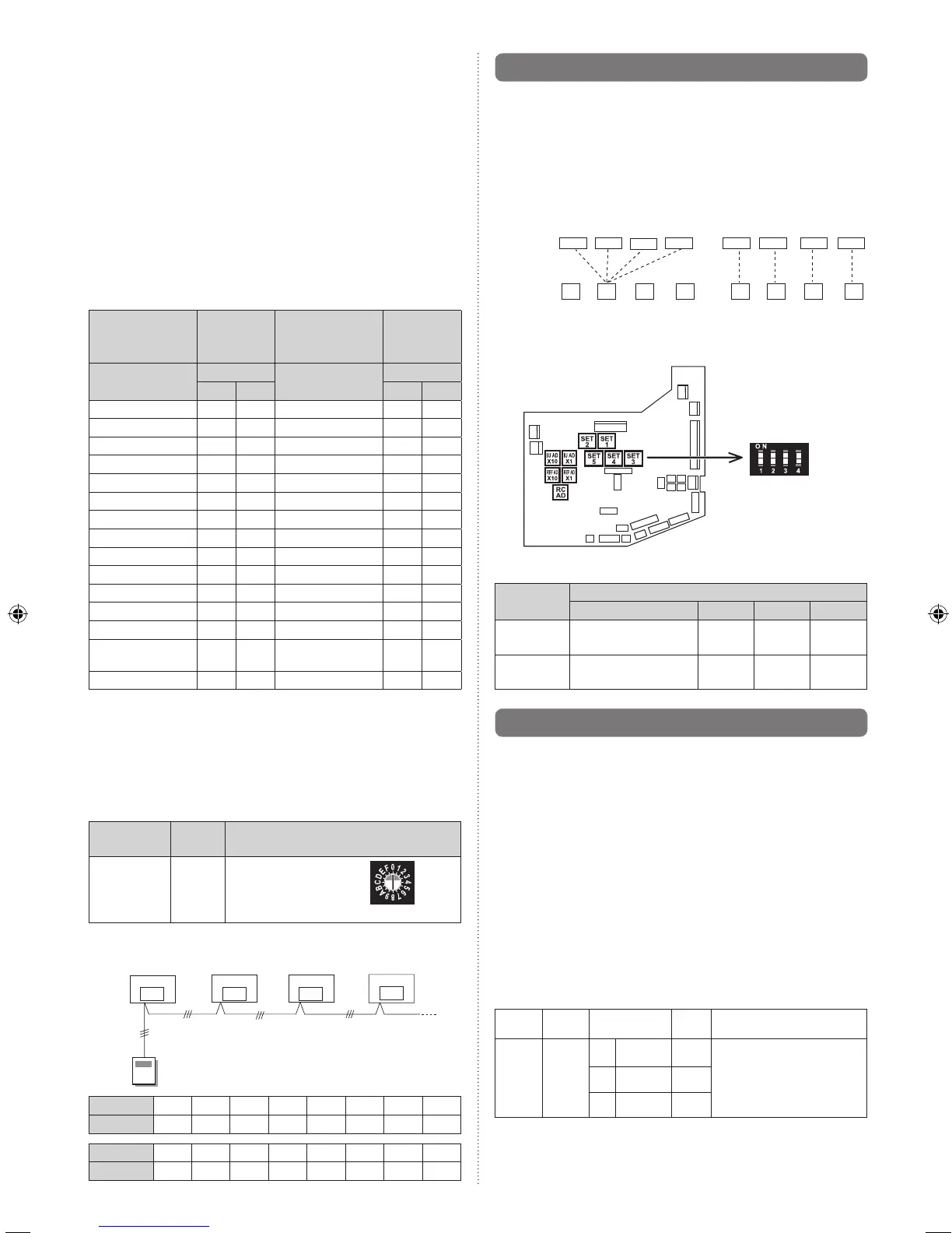
(1) Indoor unit address
Rotaryswitch(IUAD×1)......Factorysetting“0”
Rotaryswitch(IUAD×10)....Factorysetting“0”
When connecting multiple indoor units to one refrigerant
system,settheaddressatIUADSWasshowninthe
Table A.
(2) Refrigerant circuit address
Rotaryswitch(REFAD×1)......Factorysetting“0”
Rotaryswitch(REFAD×10)....Factorysetting“0”
Inthecaseofmultiplerefrigerantsystems,setREFAD
SW as shown in the Table A for each refrigerant
system.
Set to the same refrigerant circuit address as the outdoor
unit.
Table A
Address
Rotary
Switch
Setting
Address
Rotary
Switch
Setting
Refrigerant
circuit
REF AD SW
Indoor
unit
IU AD SW
×10 ×1 ×10 ×1
0 0 0 0 0 0
1 0 1 1 0 1
2 0 2 2 0 2
3 0 3 3 0 3
4 0 4 4 0 4
5 0 5 5 0 5
6 0 6 6 0 6
7 0 7 7 0 7
8 0 8 8 0 8
9 0 9 9 0 9
10 1 0 10 1 0
11 1 1 11 1 1
12 1 2 12 1 2
.
.
.
.
.
.
.
.
.
.
.
.
.
.
.
.
.
.
99 9 9 63 6 3
Dono
tsettheindoorunitaddress(IUADSW)at64to99.It
may result
failure.
(3) Remote controller address
Rotaryswitch(RCADSW)....Factorysetting“0”
When connecting multiple indoor units to one standard
wiredremotecontroller,settheaddressatRCADSWin
sequence from 0.
Setting
Setting
range
Type of switch
Remote con-
troller
address
0–15
Setting
example
0
RCAD
Example If 4 indoor units are connected.
Remote
controller
Indoor unit
Indoor unit
Indoor unitIndoor unit
RC AD SW
0
RC AD SW
1
RC AD SW
2
RC AD SW
3
RCADSW
0 1 2 3 4 5 6 7
Address 0 1 2 3 4 5 6 7
RCADSW
8 9 A B C D E F
Address 8 9 10 11 12 13 14 15
]1
7.2. Custom code setting
Selectingthecustomcodepreventstheindoorunitmix-up.
(Fig. B)
(Up to 4 codes can be set.)
Perform the setting for both the indoor unit and the remote
controller.
Fig. B
Code change
Indoor unit
Remote
controller
Confusion
• Custom code setting for indoor unit
SettheDIPSWSET3SW1,SW2,referringtotheTableB.
Dipswitch
“SET3”
ON
OFF
Table B
Custom code
A (Factory setting) B C D
DIPSW
SET 3 SW1
OFF ON OFF ON
DIPSW
SET 3 SW2
OFF OFF ON ON
]1
7.3. Function setting
• FUNCTIONSETTINGcanbeperformedwiththewiredor
wireless remote control.
(The remote control is optional equipment)
• Refertothewiredorwirelessremotecontrolmanualfor
detailedsettinginformation.(SetIUAD,REFADSWto0)
• Referto“7.1.Settingtheaddress”forindoorunitaddress
and refrigerant circuit address settings.
• TurnthepoweroftheindoorunitONbeforestartingthe
setting.
* Turning on the power indoor units initializes EEV, so make
sure the piping air tight test and vacuuming have been
conducted before turning on the power.
* Also check again to make sure no wiring mistakes were
made before turning on the power.
Function details
Function
Function
number
Setting
number
Default Details
Filter
indicator
interval
11
00 Default
○
Adjust the filter cleaning interval
notification. If the notification is
too early, change to setting 01. If
the notification is too late, change
to setting 02.
01 Longer
02 Shorter
9373870036_02_IM_en.indd 12 25/2/2552 9:17:36