En-6
1
4.2. Pipe requirement
CAUTION
•Refer to the Installation Manual of the outdoor unit
for description of the length of connecting pipe or for
difference of its elevation.
Use pipe with water-resistant heat insulation.•
CAUTION
•Install heat insulation around both the gas and liquid
pipes. Failure to do so may cause water leaks.
Use heat insulation with heat resistance above 120 °C.
(Reverse cycle model only)
In addition, if the humidity level at the installation location
oftherefrigerantpipingisexpectedtoexceed70%,
install heat insulation around the refrigerant piping.
Iftheexpectedhumiditylevelis70-80%,useheat
insulationthatis15mmorthickerandiftheexpected
humidityexceeds80%,useheatinsulationthatis20
mm or thicker. If heat insulation is used that is not as
thickasspecied,condensationmayformonthesurface
of the insulation.
In addition, use heat insulation with heat conductivity of
0.045W/(m·K)orless(at20°C).
1
4.3. Flare connection (pipe connection)
4.3.1. Flaring
• UsespecialpipecutterandaretoolexclusiveforR410A.
(1) Cut the connection pipe to the necessary length with a
pipe cutter.
(2) Hold the pipe downward so that cuttings will not enter the
pipe and remove any burrs.
(3) Insertthearenut(alwaysusethearenutattachedto
the indoor and outdoor units respectively) onto the pipe
andperformtheareprocessingwithaaretool.Usethe
specialR410Aaretool,ortheconventionalaretool.
Leakageofrefrigerantmayresultifotherarenutsare
used.
(4) Protect the pipes by pinching them or with tape to prevent
dust, dirt, or water from entering the pipes.
Checkif[L]isareduniformly
and is not cracked or scratched.
Die
Pipe
A
B
Pipe outside
diameter
[mm (in.)]
Dimension A [mm]
Dimension B
-
0
0.4
[mm]
Flare tool for R410A,
clutch type
6.35 (1/4)
0 to 0.5
9.1
9.52 (3/8) 13.2
12.70 (1/2) 16.6
15.88 (5/8) 19.7
19.05 (3/4) 24.0
WhenusingconventionalaretoolstoareR410Apipes,
thedimensionAshouldbeapproximately0.5mmmore
thanindicatedinthetable(foraringwithR410Aaretools)
toachievethespeciedaring.Useathicknessgaugeto
measure the dimension A.
Pipe outside
diameter [mm (in.)]
Width across flats
of Flare nut [mm]
6.35 (1/4) 17
9.52 (3/8) 22
12.70 (1/2) 26
15.88 (5/8) 29
19.05 (3/4) 36
4.3.2. Bending pipes
The pipes are shaped by your hands or pipe bender. Be •
careful not to collapse them.
Donotbendthepipesinananglemorethan90°.•
When pipes are repeatedly bend or stretched, the material •
willharden,makingitdifculttobendorstretchthemany
more.Donotbendorstretchthepipesmorethanthree
times.
CAUTION
•Topreventbreakingofthepipe,avoidsharpbends.
•If the pipe is bent repeatedly at the same place, it will
break.
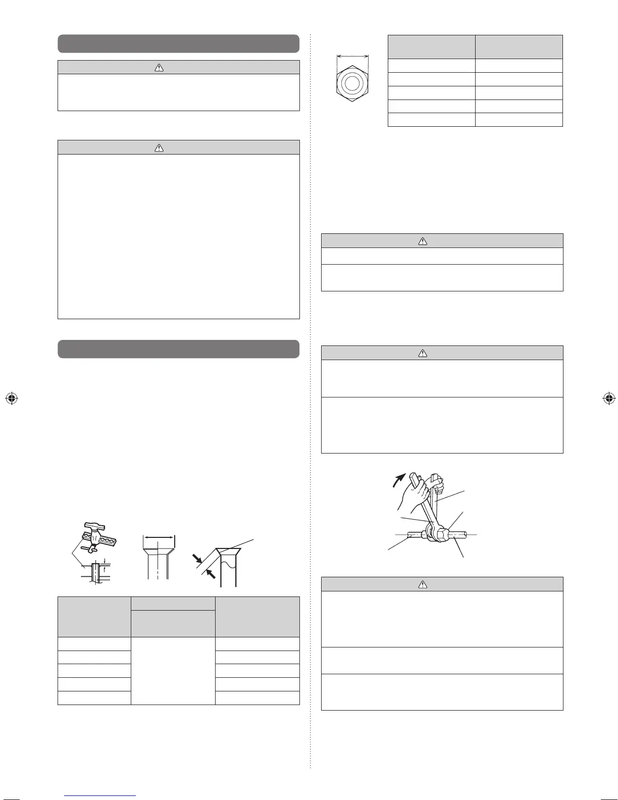
4.3.3. Pipe connection
Whenthearenutistightenedproperlybyyourhand,
hold the body side coupling with a separate spanner, then
tighten with a torque wrench.
CAUTION
•Holdthetorquewrenchatitsgrip,keepingitintheright
angle with the pipe, in order to tighten the flare nut
correctly.
•Tighten the flare nuts with a torque wrench using the
specified tightening method. Otherwise, the flare nuts
could break after a prolonged period, causing refrigerant
to leak and generate a hazardous gas if the refrigerant
comesintocontactwithaame.
Connection pipe
Torque wrench
Indoor unit pipe
(Body side)
Tighten with two wrenches.
Holding wrench
Flare nut
CAUTION
•Besuretoapplythepipeagainsttheportontheindoor
unit and the outdoor unit correctly. If the centering is
improper, the flare nut cannot be tightened smoothly.
If the flare nut is forced to turn, the threads will be
damaged.
•Donotremovethearenutfromtheindoorunitpipeuntil
immediately before connecting the connection pipe.
•Do not use mineral oil on flared part. Prevent mineral
oil from getting into the system as this would reduce the
lifetime of the units.
Width across
ats