En-5
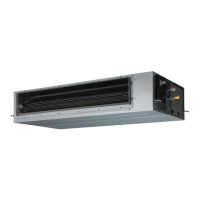
•Install the air inlet grille for air circulation. The correct
temperature can not be detected.
Unit
Duct
(Field supply)
Outlet Grille
(Field supply)
Inlet Grille
(Field supply)
(Room)
•Besuretoinstalltheairlterintheairinlet.Iftheairlter
isnotinstalled,theheatexchangermaybecloggedand
its performance may decrease.
4. PIPE INSTALLATION
]
CAUTION
•Bemorecarefulthatforeignmatter(oil,water,etc.)does
not enter the piping than with refrigerant R410A models.
Also, when storing the piping, securely seal the openings
by pinching, taping, etc.
•Whileweldingthepipes,besuretoblowdrynitrogengas
through them.
]1
4.1. Selecting the pipe material
CAUTION
•Donotuseexistingpipes.
•Usepipesthathavecleanexternalandinternalsides
without any contamination which may cause trouble
duringuse,suchassulfur,oxide,dust,cuttingwaste,oil,
or water.
•Itisnecessarytouseseamlesscopperpipes.
Material:Phosphordeoxidizedseamlesscopperpipes
It is desirable that the amount of residual oil is less than
40 mg/10 m.
•Donotusecopperpipesthathaveacollapsed,
deformed, or discolored portion (especially on the interior
surface).Otherwise,theexpansionvalveorcapillarytube
may become blocked with contaminants.
•Improperpipeselectionwilldegradeperformance.Asan
air conditioner using R410A incurs pressure higher than
when using conventional refrigerant, it is necessary to
choose adequate materials.
• ThicknessesofcopperpipesusedwithR410Aareasshown
in the table.
• Neverusecopperpipesthinnerthanthoseindicatedinthe
table even if they are available on the market.
Thicknesses of Annealed Copper Pipes (R410A)
Pipe outside diameter [mm (in.)] Thickness [mm]
6.35 (1/4) 0.80
9.52 (3/8) 0.80
12.70 (1/2) 0.80
15.88 (5/8) 1.00
19.05 (3/4) 1.20
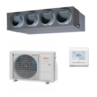
3.3.2. Leveling
Usetheprocedureinthefollowingguretoadjustthe
levelness.
AB
(Front)
Level meter
B A
Level meter
(Side)
The side A of the unit with the drain port should be slightly
lower than the opposite side B of the unit. The height
difference between sides A and B should be from 0 to 20 mm.
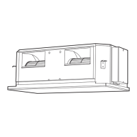
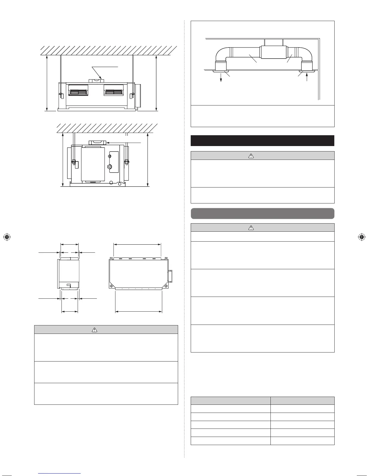
3.3.3. Mounting the duct
Followtheprocedureinthefollowingguretoinstalltheducts.
862 mm
Intakeportange
851 mm
14 mm
324 mm
∗
14 mm
∗
Spacingbetweenangeanddrainpan.
Outletportange
26 mm
295 mm
∗
27 mm
CAUTION
•Topreventpeoplefromtouchingthepartsinsidetheunit,
be sure to install grilles on the inlet and outlet ports. The
grilles must be designed in such a way that cannot be
removed without tools.
•Thestaticpressureoutsidetheunitisasfollows.
ARXC36LModel:100-200Pa
ARXC45/60LModels:100-250Pa
•Ifanintakeductisinstalled,takecarenottodamagethe
temperature sensor (the temperature sensor is attached
totheintakeportange).