En-4
•Install the indoor unit,outdoor unit, power supply cable,
transmission cable, and remote control cable at least 1 m
away from a television or radio receivers. The purpose of
this is to prevent TV reception interference or radio noise.
(Even if they are installed more than 1 m apart, you could
still receive noise under some signal conditions.)
•If children under 10 years old may approach the unit,
take preventive measures so that they cannot reach the
unit.
•Takeprecautionstopreventtheunitfromfalling.
(1)
Installtheindoorunitonaplacehavingasufcientstrength
so that it withstands against the weight of the indoor unit.
(2) The inlet and outlet ports should not be obstructed; the air
should be able to blow all over the room.
(3) Leave the space required to service the air conditioner.
(4) Install the unit where connection to the outdoor unit is
easy.
(5) Install the unit where the connection pipe can be easily
installed.
(6) Install the unit where the drain pipe can be easily installed.
(7) Install the unit where noise and vibrations are not
amplied.
(8) Take servicing, etc., into consideration and leave the
spaces.Alsoinstalltheunitwheretheltercanbe
removed.
(9) Donotinstalltheunitwhereitwillbeexposedtodirect
sunlight.
]1
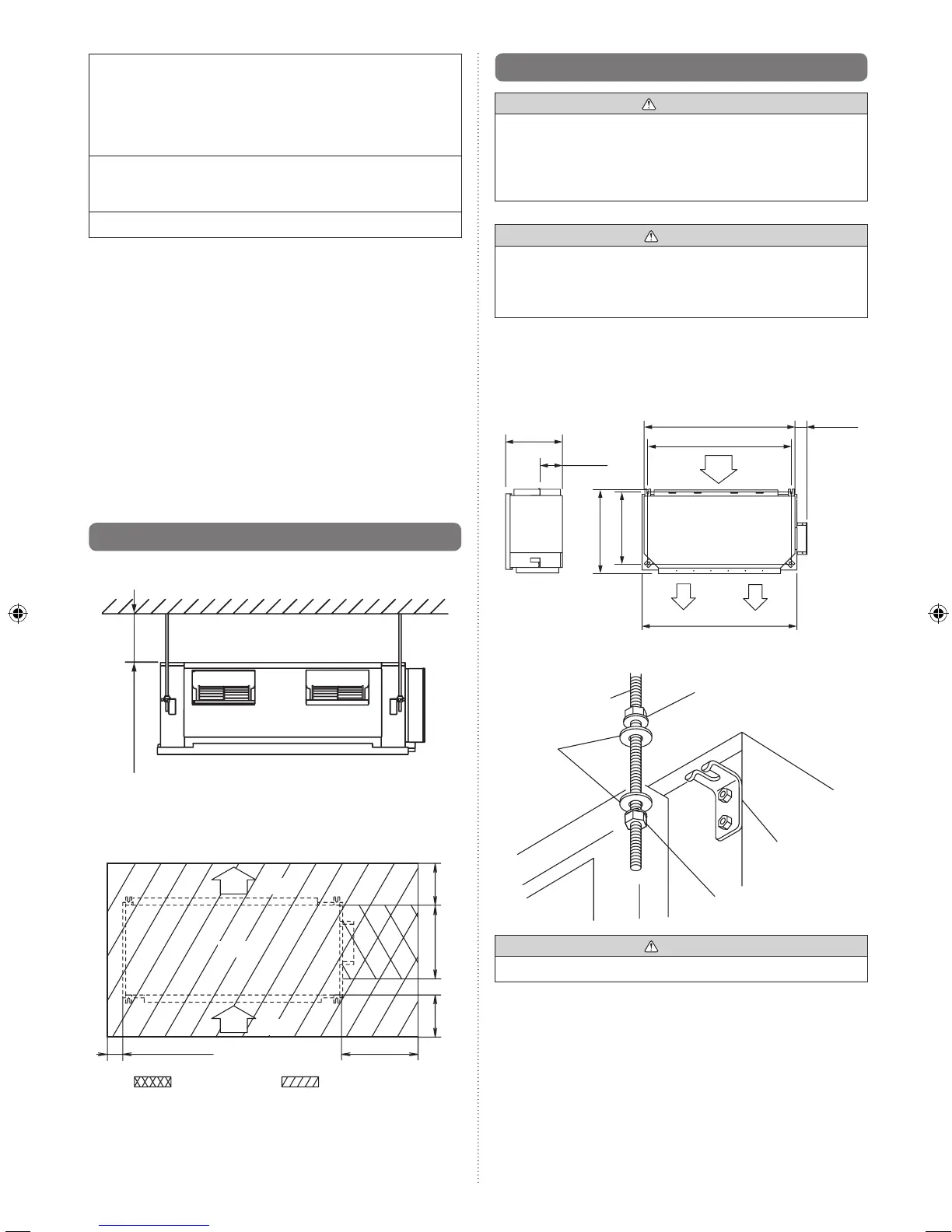
3.2. Installation dimension
Install at least 20 mm from the ceiling.
20 mm or more
Provide a service hole for inspection purposes as shown
below.
Donotplaceanywiringorilluminationintheservicespace,
as they will impede service.
30 mm or more
500 mm or more
500 mm
300 mm
or more
: Service hole : Service space
Unit
300 mm
or more
AIR
AIR
]1
3.3. Installation the unit
WARNING
•Install the air conditioner in a location which can
withstand a load of at least ve times the weight of the
main unit and which will not amplify sound or vibration. If
the installation location is not strong enough, the indoor
unit may fall and cause injuries.
CAUTION
•Conrmthedirectionsoftheairintakeandoutletbefore
installing the unit.
•Theunittakesinairfromtheevaporatorside,andexpels
it from the fan side.
3.3.1. Installing the hangers
Hanging bolt installation diagram.
1,050 mm
400 mm
155 mm
585 mm
500 mm
AIR
AIR
1,000 mm
1,080 mm
85 mm
AIR
Hanging bolt M10
(Field supply)
Special nut A (Large)
(Accessories)
Washer
(Field
supply)
Special nut B (Small)
(Accessories)
Hanger
CAUTION
•FastentheunitsecurelywithspecialnutsAandB.