En-9
CAUTION
•Groundtheunit.
Do not connect the ground cable to a gas pipe, water
pipe, lightning rod, or a telephone ground cable.
Improper grounding may cause electric shock.
•Donotconnectpowersupplycablestothetransmission
or remote control terminals, as this will damage the
product.
•Never bundle the power supply cable and transmission
cable together. Bundling these cables together will cause
miss operation.
•WhenhandlingPCB,staticelectricitychargedinthebody
may cause malfunction of the PCB. Follow the cautions
below:
•Establishagroundfortheindoorandoutdoorunitsand
peripheral devices.
•Cutpower(breaker)off.
•Touchmetalpartoftheindoorandoutdoorunitsfor
more than 10 seconds to discharge static electricity
charged in the body.
•Donottouchterminalsofpartsandpatterns
implemented on PCB.
]1
6.1. Electrical requirement
Voltage rating
230 V
Operating range
198 - 264 V
Recom-
mended cable
size (mm
2
)
Cable type Remark
Power
supply cable
2.5
Type245 IEC57
or equivalent
1ø 50 Hz
198 - 264 V
2 Cable + ground
Transmission
cable
0.33
LONWORKS
compatible cable
22 AWG
LEVEL 4 (NEMA)
non-polar 2 core,
twisted pair solid
core diameter
0.65 mm
Remote
control cable
0.33
Sheathed
PVC cable*
Polar 3 core
Twisted pair
*: Useshieldedcableinaccordancewithlocalrulesfor
remote control cable.
]1
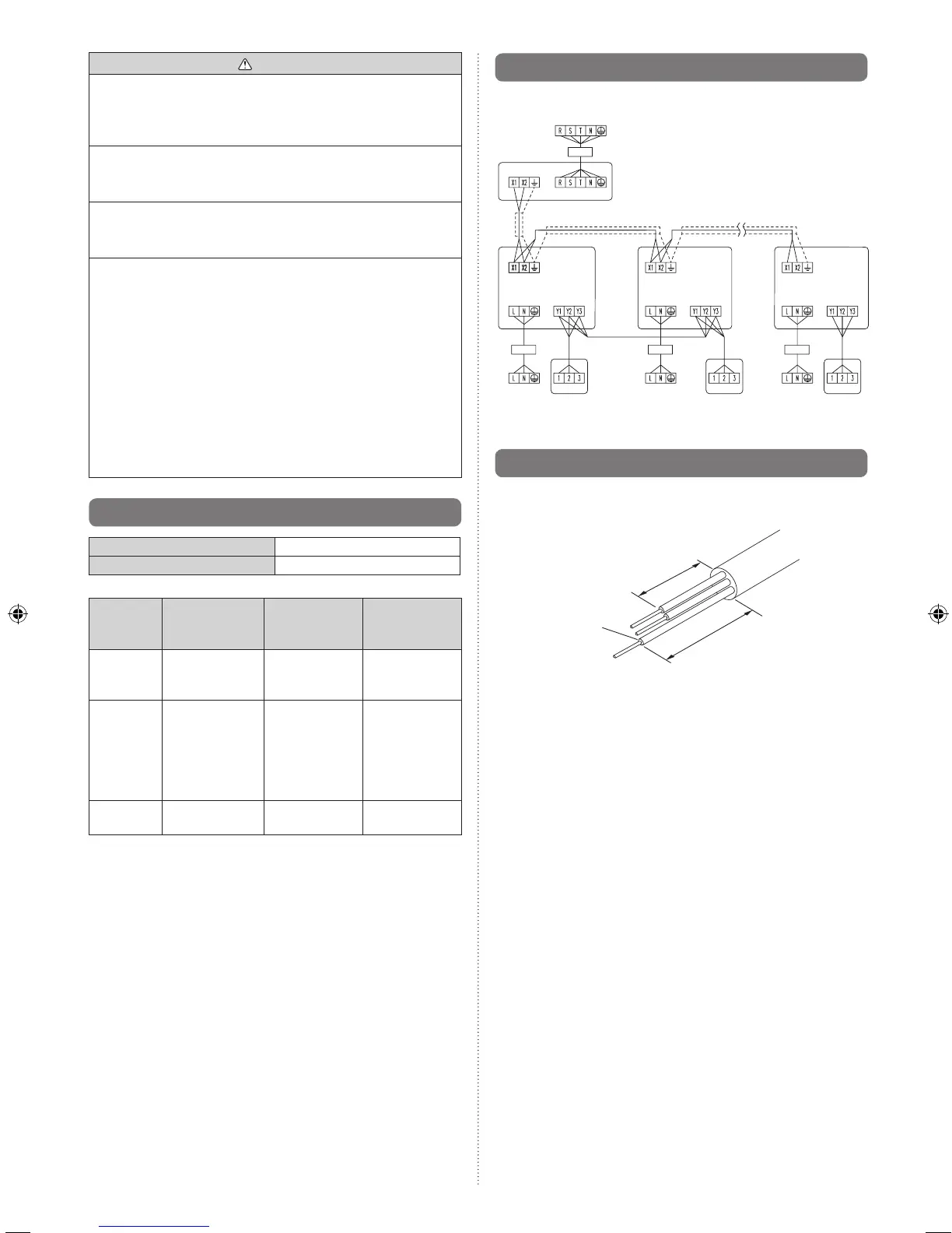
6.2. Wiring method
(EXAMPLE)
POWER SUPPLY
OUTDOORUNIT
BREAKER
POWER SUPPLY
TRANSMISSION
TRANSMISSION
POWER
SUPPLY
POWER
SUPPLY
REMOTE
CONTROL UNIT
(MASTER)
REMOTE
CONTROL UNIT
POWER
SUPPLY
REMOTE
CONTROL
TRANSMISSION TRANSMISSION
POWER
SUPPLY
POWER
SUPPLY
REMOTE
CONTROL
REMOTE
CONTROL
INDOORUNIT
POWER SUPPLY
REMOTE
CONTROL UNIT
(SLAVE)
INDOORUNIT
INDOORUNIT
BREAKER BREAKER BREAKER
]1
6.3. Unit wiring
• Beforeattachingthecabletoterminalblock.
6.3.1. Power supply cable
Power supply cable
20 mm
Earth cable
30 mm
A. For solid core wiring
(1) To connect the electrical terminal, follow the below
diagram and connect after looping it around the end of the
cable.
(2) Usethespeciedcables,connectthemsecurely,and
fasten them so that there is no stress placed on the
terminals.
(3) Use an appropriate screwdriver to tighten the terminal
screws.Donotuseascrewdriverthatistoosmall,
otherwise, the screw heads may be damaged and prevent
the screws from being properly tightened.
(4) Donottightentheterminalscrewstoomuch,otherwise,
the screws may break.
(5) See the table for the terminal screw tightening torques.
(6) Pleasedonotxtwopowersupplycableswithonescrew.