En-13
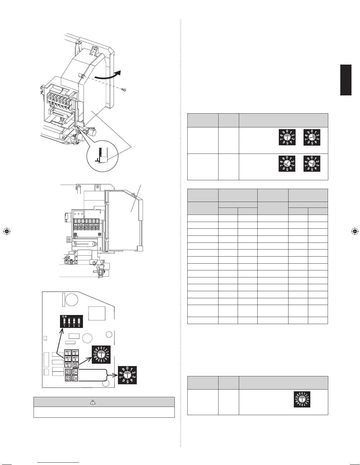
• OpenthecontrolboxcoverR.
Tapping screw
Control
boxcoverR
PCB
Rotary switch
Example:“0”
Rotary switch
Example:“0”
SW SW SW SW
1 2 3 4
Dipswitch
“SET3”
CAUTION
•Becarefulnottomakemistakesforswitchsettings.
(1) Indoor unit address
Rotaryswitch(IUAD×1)....Factorysetting“0”
Rotaryswitch(IUAD×10)....Factorysetting“0”
When connecting multiple indoor units to one refrigerant
system,settheaddressatIUADSWasshowninthe
Table A
(2) Refrigerant circuit address
Rotaryswitch(REFAD×1)....Factorysetting“0”
Rotaryswitch(REFAD×10)....Factorysetting“0”
Inthecaseofmultiplerefrigerantsystems,setREFAD
SW as shown in the Table A for each refrigerant system.
Set to the same refrigerant circuit address as the outdoor
unit.
Setting
Setting
range
Type of switch
Indoor unit
address
0–63
Setting
example
2
IUAD×10 IUAD×1
Refrigerant
circuit
address
0–99
Setting
example
63
REFAD×10 REFAD×1
Table A
Address
Rotary
Switch Setting
Address
Rotary
Switch Setting
Refrigerant
circuit
REF AD SW
Indoor unit
IU AD SW
×
10
×
1
×
10
×
1
0 0 0 0 0 0
1 0 1 1 0 1
2 0 2 2 0 2
3 0 3 3 0 3
4 0 4 4 0 4
5 0 5 5 0 5
6 0 6 6 0 6
7 0 7 7 0 7
8 0 8 8 0 8
9 0 9 9 0 9
10 1 0 10 1 0
11 1 1 11 1 1
12 1 2 12 1 2
.
.
.
.
.
.
.
.
.
.
.
.
.
.
.
.
.
.
99 9 9 63 6 3
Dono
tsettheindoorunitaddress(IUADSW)at64to99.It
may result
failure.
(3) Remote controller address
Rotaryswitch(RCADSW)....Factorysetting“0”
When connecting multiple indoor units to one standard
wiredremotecontroller,settheaddressatRCADSWin
sequence from 0.
Setting
Setting
range
Type of switch
Remote
controller
address
0–15
Setting
example
0
RCAD
 Loading...