www.furuno.com
ll brand and product names are trademarks, registered trademarks or service marks of their respective holders.
Installation Manual
ECDIS
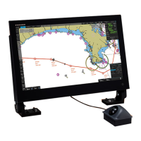
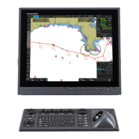
Model FMD-3100
(ELECTRONIC CHART DISPLAY AND INFORMATION SYSTEM)
SAFETY INSTRUCTIONS ................................................................................................ i
SYSTEM CONFIGURATION ........................................................................................... ii
EQUIPMENT LIST .......................................................................................................... iv
1. MOUNTING..............................................................................................................1-1
1.1 Panel Computer Unit (PCU-3000) .....................................................................................1-1
1.2 Trackball Control Unit (RCU-030)......................................................................................1-8
1.3 Sensor Adapter MC-3000S/3020D/3030D (Optional)......................................................1-10
1.4 Intelligent Hub HUB-3000 (Optional) ...............................................................................1-11
1.5 Mounting the Switching Hub HUB-100 (Optional)............................................................1-12
1.6 Radar Connection Box RCB-002 (Optional) ....................................................................1-13
2. WIRING....................................................................................................................2-1
2.1 Panel Computer Unit PCU-3000........................................................................................2-3
2.2 Sensor Adapters (Optional) .............................................................................................2-11
2.3 Intelligent HUB HUB-3000 (Optional) ..............................................................................2-27
2.4 Radar Connection Box RCB-002 (Optional) ....................................................................2-28
APPENDIX 1 JIS CABLE GUIDE .............................................................................AP-1
APPENDIX 2 ROD TERMINALS .............................................................................AP-2
APPENDIX 3 DIGITAL INTERFACE ........................................................................AP-7
APPENDIX 4 RA/IF BOARD JUMPER VALUES ...................................................AP-20
PACKING LISTS ......................................................................................................... A-1
OUTLINE DRAWINGS ................................................................................................ D-1
INTERCONNECTION DIAGRAMS.............................................................................. S-1