Operators and Technicians Manual
© 2002 – 2007 FutureLogic, Incorporated. All Rights Reserved. MNL Page 11 of 52 12/07/2007
MNL-000003 REV.N
4 Ports and Dip Switches
Introduction
This chapter describes the interface connectors and port pin-outs for each model of the
printer. For complete electrical specifications on these ports, refer to Appendix A in the
Developers Manual (MNL-000004) for the power connector.
There are two models of the PSA-66-ST2 printer:
• PSA-66-ST2N. Netplex Interface. See page
12.
• PSA-66-ST2R. RS232 Interface. See page
16.
Note: While PSA-66-ST2 refers to both the PSA-66-ST2R and PSA-66-ST2N versions of the
printer, this manual is written primarily for the RS232 interface. For additional
information on the Netplex interface, please contact International Game
Technology.
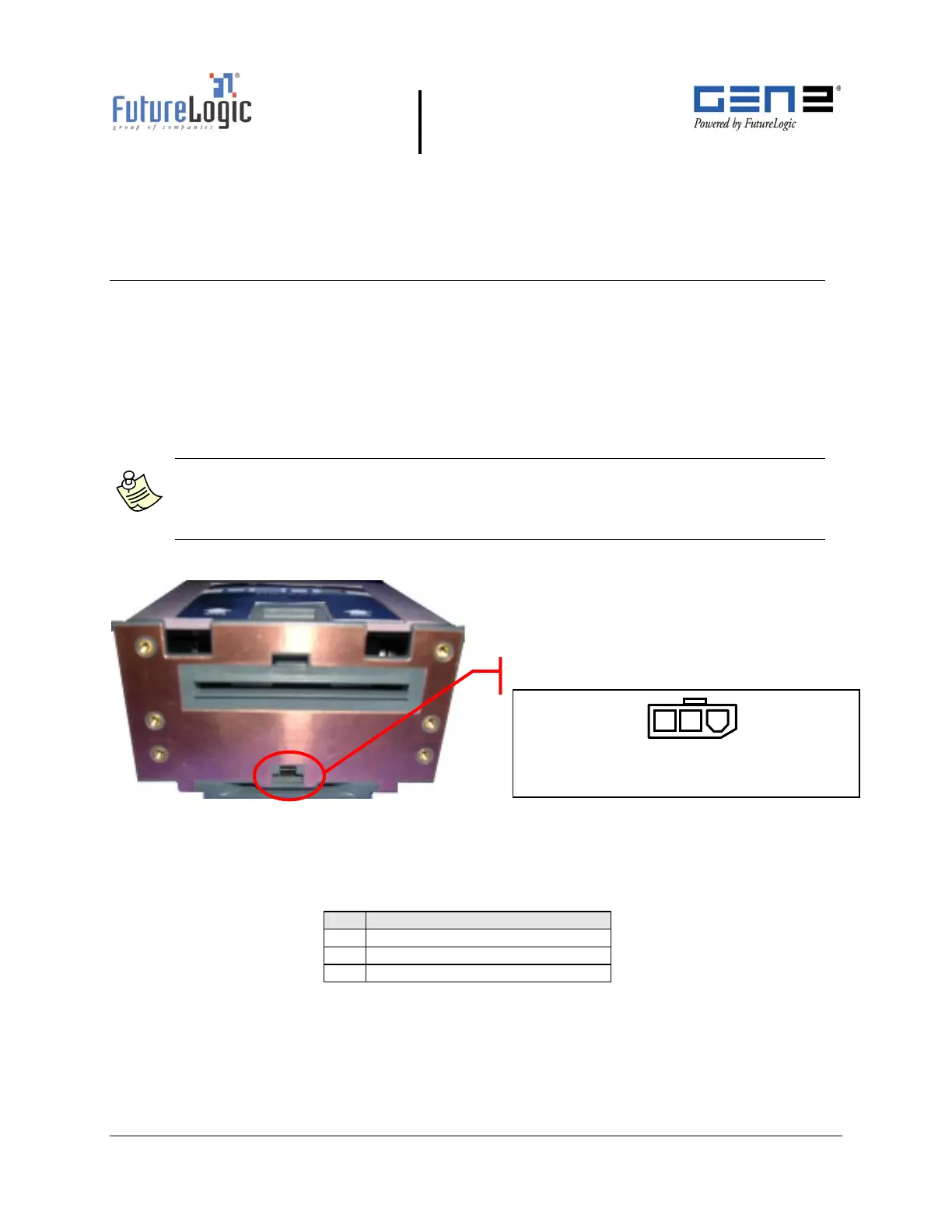
Front Bezel Port (All Models)
Figure 4-1 Front Bezel LED Control Port (All Models)
Table 4-1 lists information on the LED bezel port on the GEN2 printer. This is an open drain
modulated high side drive 25VDC port capable of driving up to a maximum 1.5A.
Table 4-1 Front Bezel LED Control Port Pins (All Models)
Pin Function
1 Switched 25VDC, 100mA Min
2 BGND
3 Frame (Chassis) Ground
Connector: Molex Micro-Fit 43640-0301
Mate: Molex Micro-Fit 43645-0300
Bezel LED Control Port
1
2