Operators and Technicians Manual
© 2002 – 2007 FutureLogic, Incorporated. All Rights Reserved. MNL Page 13 of 52 12/07/2007
MNL-000003 REV.N
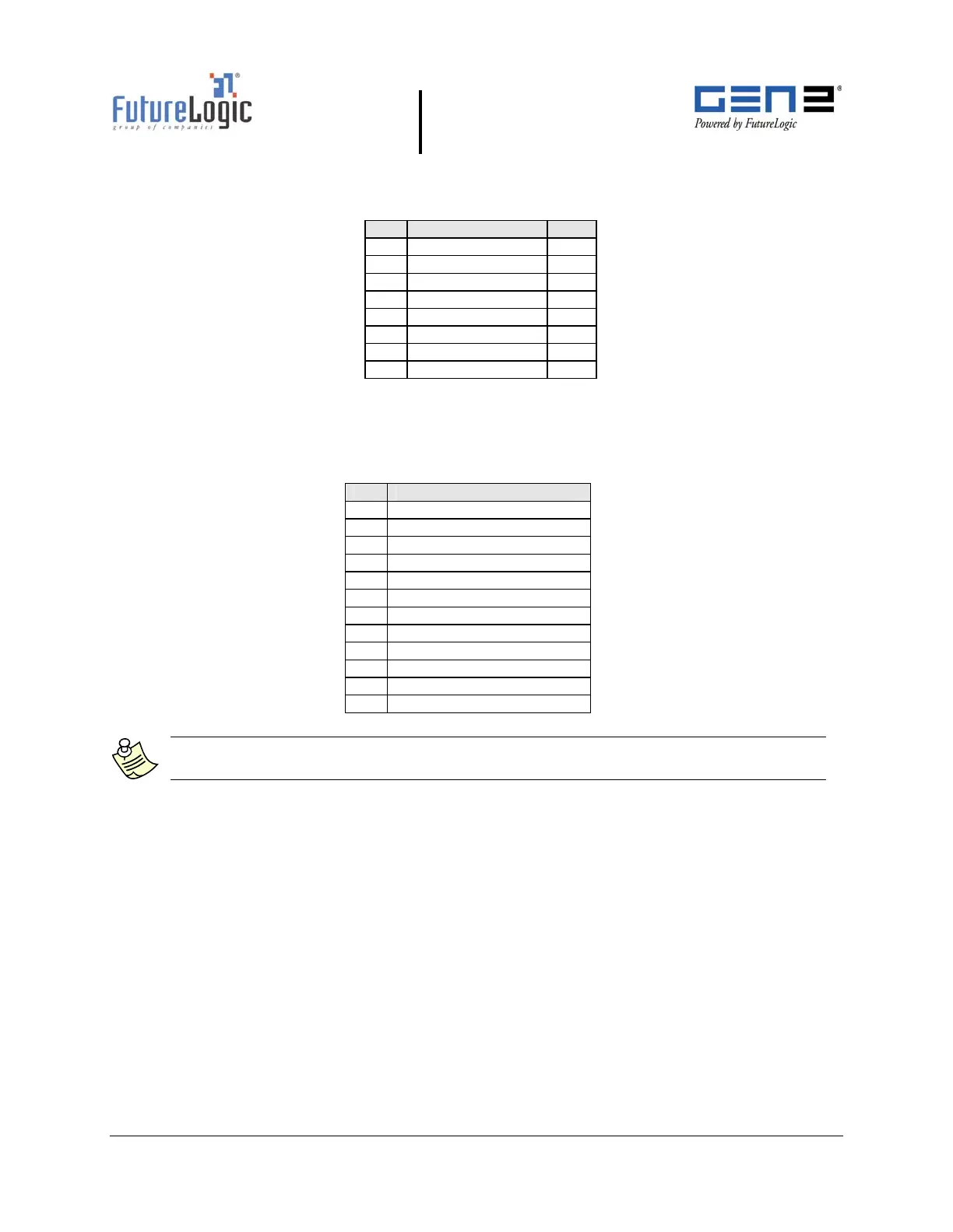
Table 4-4 Netplex Power/COMM Port Pin-out
Table 4-5 lists the pin-out of the 12 pin base port. The Modulated +24VDC pin has the same
function as the bezel port pin.
Table 4-5 12 Pin Netplex Base Port Pins
Pin Function
1 BGND (+24V Return)
2 NETPLEX RXD
3 +13VDC
4 SWITCHED +24VDC
5 No Connect
6 MRESET
7 NETPLEX TXD
8 +24VDC
9 No Connect
10 RX2
11 TX2
12 AGND
*I/O viewed from the printer
Note: The Bezel port on the rear of the printer is identical in function and
characteristics to the one on the front of the printer.
Pin Function I/O*
1 MRESET I
2 Netplex TXD I
3 +13V -
4 Netplex RXD O
5 NETGND -
6 +25VDC -
7 BGND -
8 No Connect -