Operators and Technicians Manual
© 2002 – 2007 FutureLogic, Incorporated. All Rights Reserved. MNL Page 22 of 52 12/07/2007
MNL-000003 REV.N
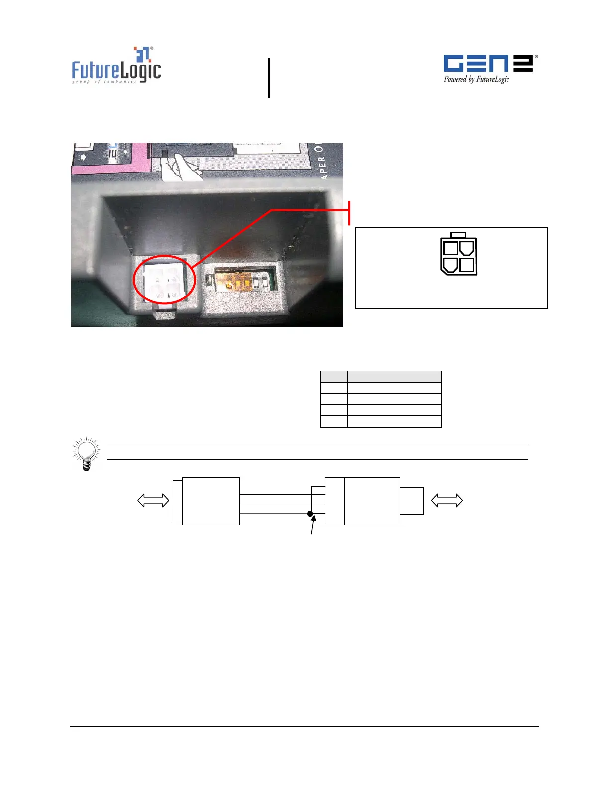
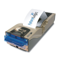
To use this port, slide the printer out until the upload port (shown in the following figure) is
visible. Then plug an appropriate upgrade cable into the printer. This connection may be
made while the power is on.
Figure 4-10 RS232 Firmware Upload Port
Table 4-19 Firmware Upload Port Pin-out
Tip: Use the following diagram to make an upload cable.
Figure 4-11 Upload Cable Diagram
DB-9
Female
Connect to PC
serial port
Molex
Mini-Fit
Connector
Connect to printer
upload port
1
2
3
4
RX
X
Tie pin 1 to 4
GND
1
3
2
4
Pin Function
1 Port Select
2 RX
3 TX
4 GND
Firmware Upload Port
Connector: Molex Mini-Fit Jr. 39-31-0040
Mate: Molex Mini-Fit Jr. 39-01-3048