Page No. 14
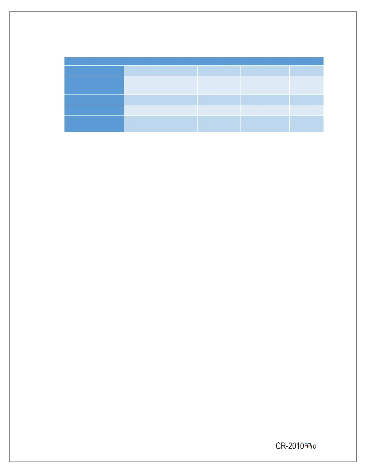
Table 4 Connection Notations
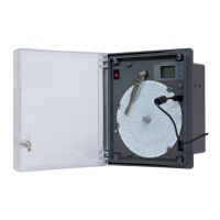
➢ The connections for Main’s supply, Door switch input, 12VDC battery connection and
sensor input are shown in Figure 6. As per the figure the live, neutral & earth from the
mains cord are connected to L, N & E respectively.
➢ Ensure that the bared ends of the mains cord are fully inserted into the mains connector
and no loose/poor connection.
➢ Also connect the Earth wire of the cable to the Earthing terminal given on body of the
recorder.
➢ Table 4 shows the connection notations for Main’s supply, Door switch input and sensor
input.
Sensor Wiring:
➢ The connection of the recorder to a proper safety earth ground is essential. Such
connection not only reduces the possibility of electric shock, but also provides the
required return for the recorder line power filters.
➢ All local electrical codes of practice must be followed when installing any instrumentation.
Please refer to the back panel of recorder to know the type of sensor input.
➢ When wiring RTDs, lead length and diameter must be chosen such that lead length are
equal and that each lead exhibits no more than resistance of 10 Ω between the recorder
and the RTD (Pt-100).
➢ For Input connections, high quality, low resistance contacts must be used which are
suitable for dry operations.
 Loading...