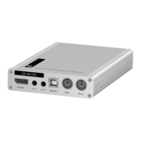
Target module »DP-HR-U-CPU-Fiber-MC2-UC«
49 · Target and user modules (DP-HR-U)
Mouse: Use the green plug of an optional Twin-PS/2 cable to connect the computer’s
PS/2 mouse interface to this interface.
Connections to the matrix switches
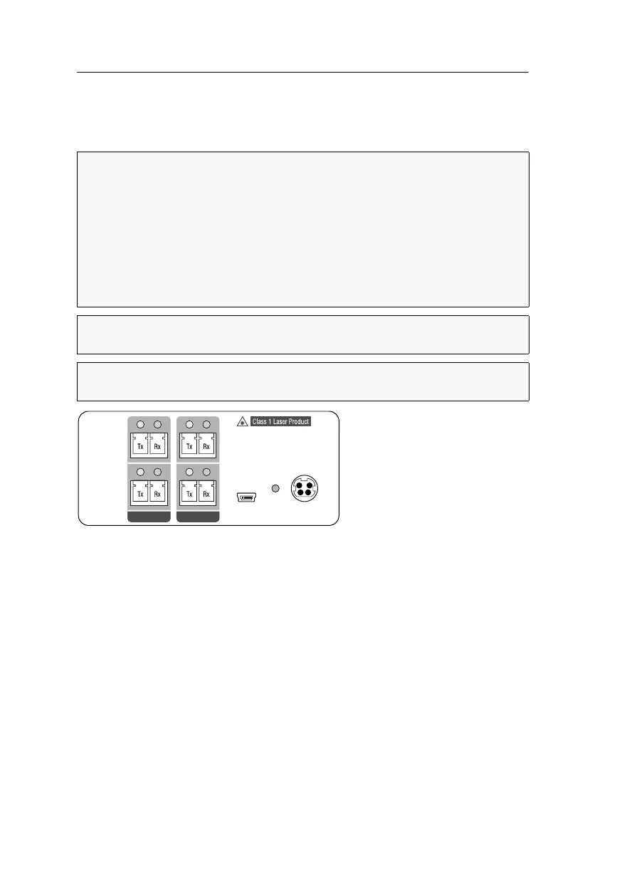
Connecting the first matrix switch
Trans. 1|Channel 1|Tx: Insert the LC plug of a compatible optical fibre cable. Connect
the other end of the cable to the
Rx interface of a Dynamic Port provided at the first
matrix switch.
Trans. 1|Channel 1|Rx: Insert the LC plug of a compatible optical fibre cable. Connect
the other end of the cable to the
Tx interface of the same Dynamic Port provided at the
first matrix switch.
Trans. 1|Channel 2|Tx: Insert the LC plug of a compatible optical fibre cable. Connect
the other end of the cable to the
Rx interface of another Dynamic Port provided at the
first matrix switch.
Trans. 1|Channel 2|Rx: Insert the LC plug of a compatible optical fibre cable. Connect
the other end of the cable to the
Tx interface of the same Dynamic Port provided at the
first matrix switch.
The devices use components with laser technology which comply with laser
class
1.
They meet the requirements according to EN 60825-1:2007 and EN 60825-
2:2004+A1:2007
as well as U.S. CFR 1040.10 and 1040.11.
Mind the following instructions when dealing with laser beams:
Avoid direct eye exposure to beam on page 3
Always connect optical connections or cover them with protection caps on page 3
Only use G&D certified transmission modules on page 3
NOTE:
Use optical fibres with LC plugs to connect the devices. The cables are
available as accessories.
IMPORTANT:
For each matrix switch, connect only one Trans. interface of the tar-
get module!
Channel 1
Channel 2
Service
Power In
Power
Trans. 1Trans. 2
 Loading...