GatesAir PTR-255 Program Audio Codec Module
Intraplex Products Issue 2.1, February 2006
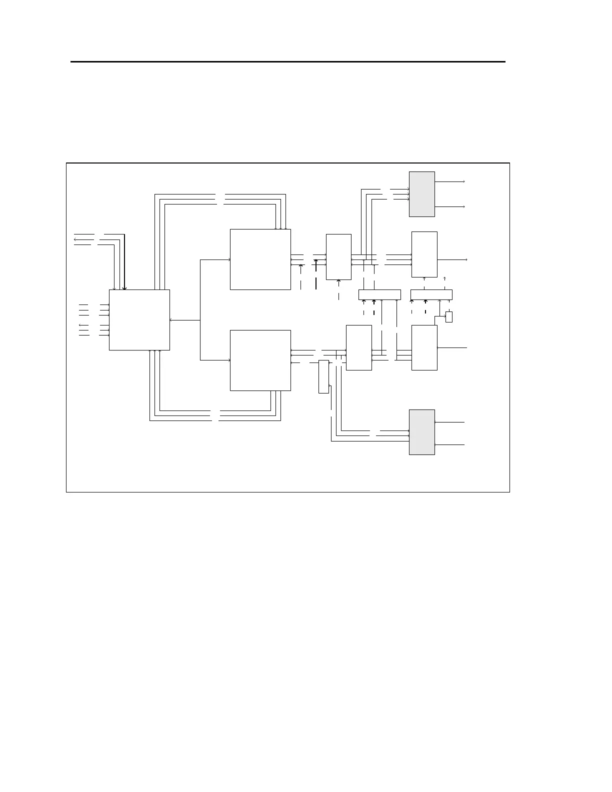
2 Functional Description
Figure 1-1 is a functional block diagram of the PTR-255.
SCI
SSI1 Tx
SSI1 Rx
SSI0 Tx
SSI0 Rx
SSI1 Rx
SSI0 Tx
SSI1 Tx
SSI0 Rx
AK4324
AK5392
HSI
HSI
MM I/O
SSI1|SSI0
Tx | Rx
SCI
SCI
AD1890
AD1890
CS8402
CS8412
Decoder
Encoder
Host
tdmrx
rxohd
rxclk
tdmtx
txohd
txclk
CLK
Tx
Rx
clk
sync
data
clk
sync
data
data
sync
clk
data
sync
clk
S
R
C
S
E
L
clk
sync
data
sync
clk
data
sync
clk
Fs 64Fs
Fs
64Fs
16 Mhz
x8
AES/EBU
OUT
AES/EBU
IN
Left Out
Right Out
Left In
Right In
128Fs
48k,32k,24k
48k,44.1k,32k
(Recovered)
A
E
S
S
Y
N
C
Fs
64Fs
sync
clk
sync
clk
data data
data
/2
128Fs
256Fs
256Fs
128Fs
A
E
S
S
Y
N
C
256Fs
(to AK4324)
SSI1|SSI0
Rx | Tx
Figure 2-1
PTR-255, Block Diagram
2.1 Audio I/O
The audio input format for the PTR-255 can be either analog or AES/EBU digital; both analog
and AES/EBU digital output formats are available simultaneously. The audio input and output
connections are via a module adapter at the rear of the multiplexer. Details on these input and
output connections appear in Section 5, Module Adapters and Interface Options.
2.2 Analog Audio
Analog audio input is a balanced termination with a user-selectable impedance of either 600 or
greater than 10k . Impedance selection is by a jumper setting on the module adapter.
 Loading...