GatesAir PTR-255 Program Audio Codec Module
Intraplex Products Issue 2.1, February 2006
2.10 Drop and Insert Operation
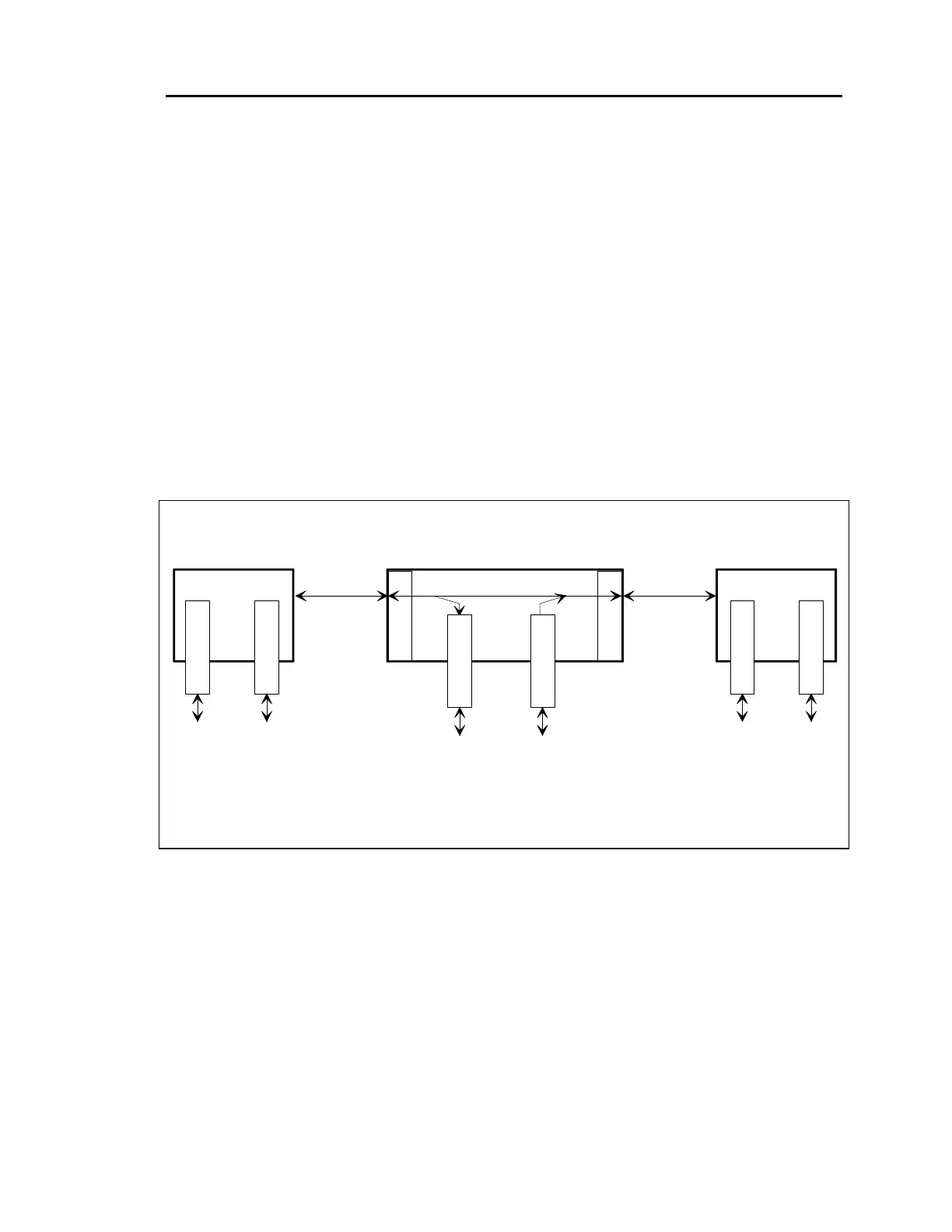
A drop and insert multiplexer operates at a central point on a three (or more) point system. In the
example shown in Figure 2-2, Site 2 has a drop and insert multiplexer whose DI-A port is
connected to the transmission line to Site 1 and whose DI-B port is connected to the transmission
line to Site 3. Individual payload channels may connect Sites 1 and 2, 1 and 3 or 2 and 3.
Also, when the transmission is one-way only, a PTR-255 may be installed at Site 1 or Site 3 and
its output can be received by PTR-255 modules at both of the other sites, without the need for
tandem decoding and re-encoding.
In the drop and insert multiplexer at Site 2, a PTR-255 module can be set to
transmit either toward Site 1 or toward Site 3, but not both.
When a PTR-255 is installed in a terminal multiplexer (Site 1 or Site 3), its TERM switch must
be set DOWN. However, when it is installed in a drop and insert multiplexer (Site 2) the TERM
switch setting must be DOWN to transmit and receive via the DI-A port (toward Site 1) and UP
to communicate via the DI-B port (toward Site 3). Drop and insert operation is not applicable to
IntraLink ISDN multiplexers.
Site 2
Drop and Insert Multiplexer
Through Channels
Site 3
Terminal
Multiplexer
Drop and
Insert
Channels
T1, 2 MB, or
Other
Aggregate
Circuit
D/I
A
D/I
B
Site 1
Terminal
Multiplexer
To
Site
2
(TERM
Switch
DOWN)
T1, 2 MB, or
Other
Aggregate
Circuit
P
T
R
2
5
5
To
Site
3
(TERM
Switch
DOWN)
P
T
R
2
5
5
To
Site
1
(TERM
Switch
DOWN)
P
T
R
2
5
5
To
Site
2
(TERM
Switch
DOWN)
P
T
R
2
5
5
To
Site
3
(TERM
Switch
UP)
P
T
R
2
5
5
To
Site
1
(TERM
Switch
DOWN)
P
T
R
2
5
5
Figure 2-2
Example of a Three-Point System Using Drop and Insert
 Loading...