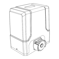
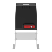
GA600AC Sliding Gate Opener User Manual
installed to left-hand installed, you should only set it on the control board, no need to switch over the
two magnet limit switch stops. So it’s extremely important to decide the limit switch stops position
and make sure the polarities are 100% correct.
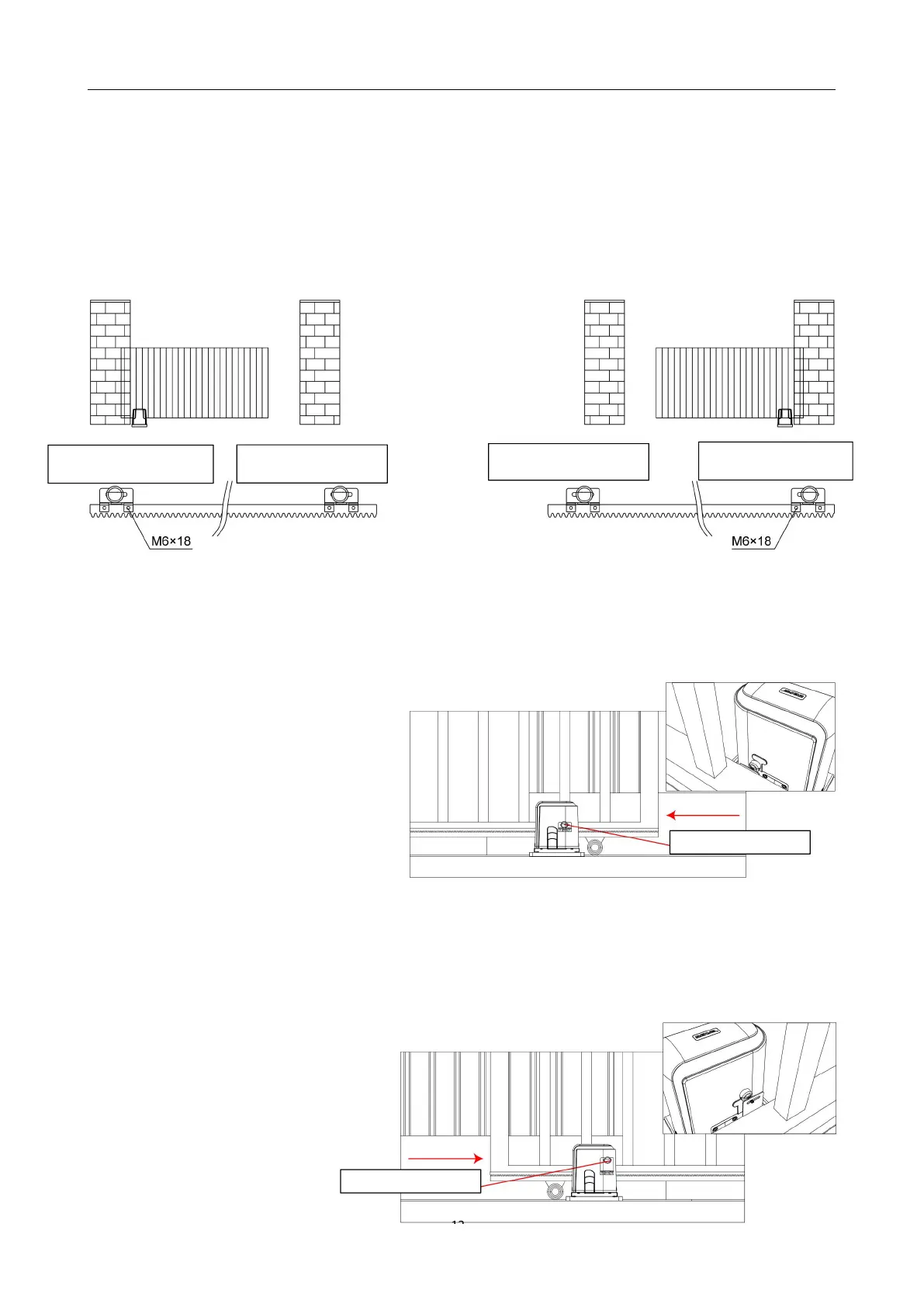
Installation drawing of limit switch stop polarities for right-hand and left-hand:
Figure 12
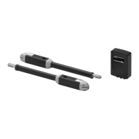
The magnet holder is mounted as shown
Setting the Limit Switch Stops
Closed Position
· Position gate 150-200mm back from
the magnet bracket closed position. This
will help in making sure you do not slam
the gate into the end stop/catch when
setting the closed position under power.
· Fit magnet bracket onto the top of gear rack at the point where it meets the Magnetic limit switch
on the motor.
· Tighten locking screws of limit switch stop.
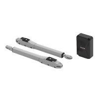
Open Position
· Position gate 150-200mm back
from the magnet bracket open position.
This will help in making sure you do not
slam the gate into the end stop/catch