Puma II User’s Guide 2-3
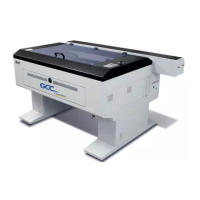
Third, (For Puma II 132S only) position the stand beam perpendicularly to part 3 and put
the screws into the holes and tighten them as Figure 2-2-1.
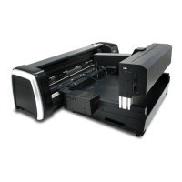
Step 4
Move the cutting plotter from the carton. Put it on the stand, then
Insert the screws into the holes on plotter’s bottom as Figure 2-3.
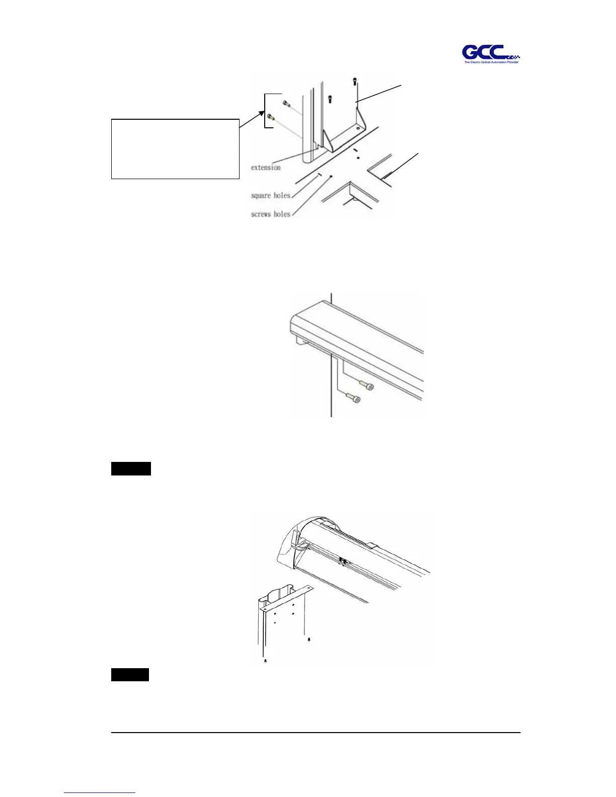
Step 5
Insert the roll holder support with the screws into the holes of the stand then tighten
them as Figure 2-4. You can decide roll holder support’s position by inserting into
Figure 2-2-1
(Only for Puma II-132S)
Figure 2-2
3
H-stand
Figure 2-3
Only Puma II 60 has side screws.
Puma II 132S doesn’t has side
screws.
 Loading...