Installation
4
Installing the base unit
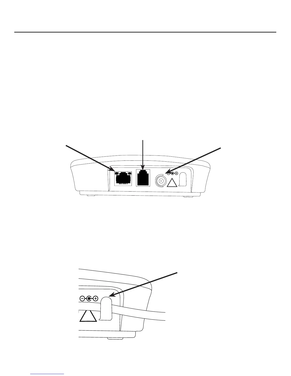
1. Connect one end of the Ethernet cable to the Ethernet cable jack (WAN) on the
2. Connect one end of the telephone line cord to the Telephone line jack on the base
unit and the other end to a telephone wall jack.
3. Connect the smaller end of the power adapter to the Power adapter jack on the
base unit and the other end to an active electrical outlet.
NOTE: Emergency calls via the landline are only possible when the base unit is plugged into an electrical outlet
receiving power and the landline is connected to a working telephone jack.
Figure 3 shows the back of the base unit and the positions of the jacks.
WAN TELLINE
POWER 6VDC
!
Ethernet
cable jack
Telephone line jack
Power adapter
jack
Figure 3
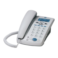
Note that there is a power cord catch at the back of the base unit on the right side of
the power adapter jack. This is used for threading the power cord that comes out of
the power adapter jack. If necessary, you can also tie the excess cord with a twist tie.
Figure 4 shows the power cord threaded through the power cord catch.
POWER 6VDC
!
Figure 4
Power cord catch
Installation