Illustration of the ÄKTA go
instrument
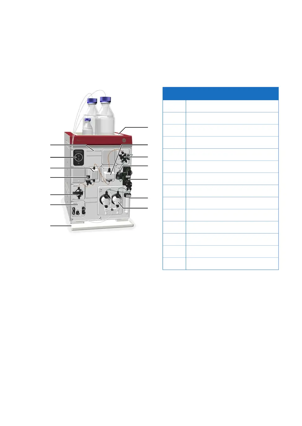
The illustration below shows the ÄKTA go instrument after installation.
FunctionPart
Pump1
Pump rinsing solution tube2
Pressure monitor3
Mixer4
Injection valve5
UV monitor6
Top tray7
Holder rails8
Instrument control panel9
Conductivity monitor10
Flow restrictor11
Outlet valve12
Inlet valve13
Bottom tray14
Illustration of the instrument
control panel
The instrument control panel is located to the upper left on the front of the instrument.
It shows the current status of the system using LED light and status text. The pause and
continue buttons can be used to control an ongoing run.
Control panel buttons can be locked using the UNICORN software.
Note:
ÄKTA go Operating Instructions 29360951 AC 19
3 System description
3.1 ÄKTA go

 Loading...


