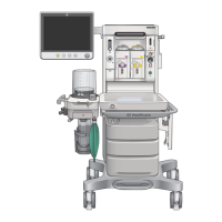
Anesthesia system display
3.1
3.9
VCV 500 12 1:2 Off Off 40
12
16
45
0.1
5.1
6.3
14
521
3
6
03:18
40
1200
0.5
1
5
10
15
5
0
60
-60
10
0
20
-20 100
0
20
40
60
80
3.0
10.0
Audio Pause
Alarm Setup
System
Setup
Next Page
Trends
Spirometry
Procedures
End Case
PmaxPEEPTpauseRR I:ETVMode
FGO2 %
Ventilator Off: Volume Control
Flow
Paw
CO2
Gases %
CO2 %
Flow l/min
Paw cmH2O
Resp
00:00:00
Start
8.0
21
2.0
40
Total Flow
8.3
55
Auto Limits
0
0
1:52
1.3
12
2
7
9
11
5 6
3
8
10
AC.24.008
0.0 0.0
0.0
Agent %
11
1. Audio pause symbol and
countdown clock
Indicates when alarm audio is paused and the countdown clock until audio is
on.
2. Alarm message fields Displays the active alarms.
3. Waveform fields Displays the waveforms of measured values. For example: Paw, Flow, and
CO2.
4. General message fields or lock
touchscreen indicator
Displays general messages and the touchscreen lock indicator.
5. Measured values fields Displays the measured values. For example: Paw, Flow, and CO2.
6. Clock Displays the current time.
7. Function keys Functions available are: Audio Pause, Alarm Setup, Auto Limits, System
Setup, Next Page, Trends, Spirometry, Procedures, Timer, Start, and End
Case.
8. Digit fields Contains information for Loops, Resp, Agent, Gas Supplies, Flow, and Gases.
9. Ventilation mode Displays the selected ventilation mode. For example: Ventilator Off and Volume
Control.
2 System controls and menus
2076152-001 2-15

 Loading...


