Chapter 2: Installation
Concord 4 Installation Manual 13
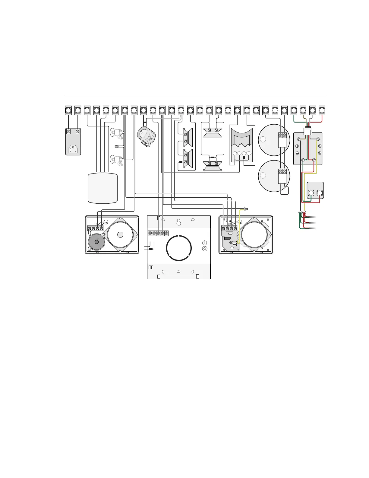
Panel terminals
Figure 5 below shows an overview of panel terminals. The following sections provide
details on how to connect devices to the panel.
Figure 5: Panel terminals
TIP
(+)
RING
(-)
BRN
GRY
GRN
RED
(-)
(+)
(-)
(+)
_
+
NC
COM
SW SW GND #1 #2
+12V - Red
BUS A - Green
BUS B - White or Yellow
GND - Black
1
2
3
4
5
6
789
10
11 12 13
14
15 16 17
18
19
20
21
22
23 24
25 26 27
28
16.5 VAC
GND
+12V
A
B
SPKR SPKR
OUT1 OUT2 +12V MIC GND
ZONE1 ZONE2
GND
ZONE3
ZONE4
GND
ZONE5 ZONE6
GND
ZONE7 ZONE8
GRN
BRN
GRY RED
Zones
The panel comes with factory programmed onboard hardwired zones. Install 2 kohm,
end-of-line (EOL) resistors on all unused factory programmed onboard hardwired
zones. If you don’t want to install EOL resistors, delete any unused zones from
memory.
Zone inputs 1 through 8 are supervised using the included 2-kohm, end-of-line
resistors at the last device on each circuit. All eight zones accept either normally open
(NO) or normally closed (NC) detection devices.

 Loading...