Chapter 2: Installation
22 Concord 4 Installation Manual
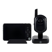
Figure 15: Installing SuperBus 2000 modules
SuperBus 2000 2-amp power supply (600-1019)
Refer to the power supply documentation for the mounting procedure. Connect the
power supply to the panel terminals and devices to be powered as shown in
Figure 16 below.
Note: Do not connect power (AC and battery) to the power supply until the panel is
ready for power-up. For power supply AC and battery connections, refer to the power
supply documentation.
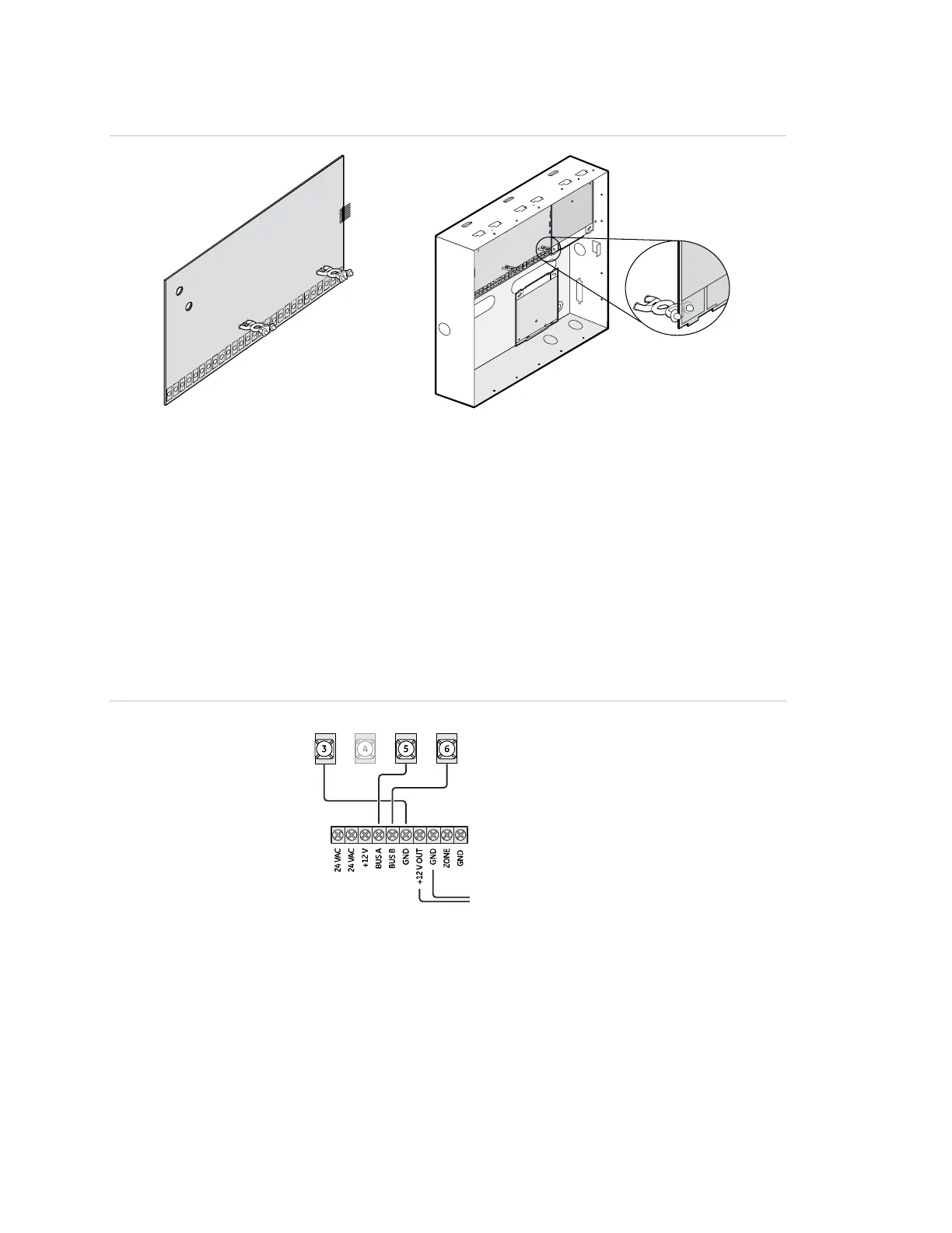
Figure 16: Wiring the SuperBus 2-amp power supply to the panel
Panel terminals
Power supply terminals
To power inputs on devices
GND +12V A BUS B
SuperBus 2000 transceiver modules
The transceiver expands RF reception range when placed near sensors on the fringe
of panel RF reception. Refer to the transceiver documentation for mounting
information.
Connect the transceiver (up to four) to the panel as shown in
Figure 17 on page 23.

 Loading...