Chapter 2: Installation
Concord 4 Installation Manual 23
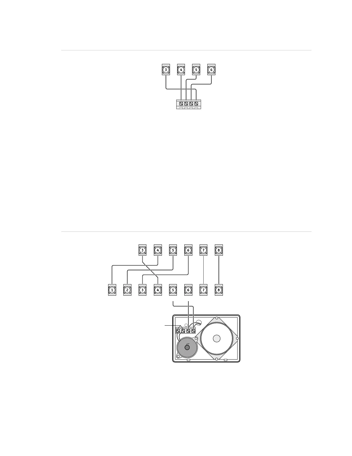
Figure 17: Wiring transceivers
+12V
A
B
GND/COM
Panel terminals
Transceiver terminals
GND +12V A BUS B
SuperBus 2000 voice-only module
The module can be mounted inside or outside of the control panel cabinet. Refer to
the documentation included with each module, for complete mounting instructions.
For RJ-31X connections, see “RJ31X phone jack” on page 27.
The module requires panel power and bus connections, and speaker connection
through panel terminals as shown in Figure 18 below.
Figure 18: Wiring for the voice-only module
Panel terminals
Module terminals
Not used
GND +12V A BUS B SPKR SPKR
+12V A BUS B GND SPK 1 SPK 2 AUD 1 AUD 2
SuperBus 2000 phone interface/voice module
The phone interface/voice module includes two backplates for mounting the module
inside the control panel cabinet. You may also mount the module outside of the

 Loading...