GEK-106310AB F650 Digital Bay Controller 7-45
7 IEC 61850 PROTOCOL 7.2 IEC 61850 PROFILE FOR F650
7
Note: actVal in BCR is imlemented as INT32.
In the F650 there are up to 16 configurable switchgears. Currently four XSWI and four CSWI are implemented and mapped
to first nine switchgears in F650. XSWI and CSWI Logical Nodes can be seen as paired objects in F650 as one pair of
XSWI and CSWI map to the same swithcgear. XSWI1 and CSWI1 map to Switchgear1, XSWI2 and CSWI2 map to
Switchgear2, etc. The difference between XSWI and CSWI in F650 is that control commands cannot be sent directly via
XSWI LN. Control commands have to be sent via CSWI LN.
In F650 relay the Circuit Breaker (XCBR1 Logical Node) by default is mapped to first switchgear (exactly like XSWI1 and
CSWI1 LNs). However it is possible to map the Circuit Breaker to any of the 16 switchgears of F650 relay. It can be done by
modification of the following setting: Setpoint->System Setup-> Breaker Settings->Number of Switchgear.
In XCBR LN for "Pos" controllable attribute all possible control models are applicable:
• "direct-control-with-normal-security"
• "SBO-control-with-normal-security"
• "direct-control-with-enhanced-security"
• "SBO-control-with-enhanced-security"
The sboTimeout attribute for Pos is configurable in a range from 500 ms to 60 seconds.
The sboClass attribute for Pos can only have value "0" (operate-once).
2.7.2 XSWI (Circuit switch)
In the F650 there are up to 16 configurable switchgears. Currently four XSWI and four CSWI are implemented and mapped
to first nine switchgears in F650. XSWI and CSWI Logical Nodes can be seen as paired objects in F650 as one pair of
XSWI and CSWI map to the same swithcgear. XSWI1 and CSWI1 map to Switchgear1, XSWI2 and CSWI2 map to
Switchgear2, etc. The difference between XSWI and CSWI in F650 is that control commands cannot be sent directly via
XSWI LN. Control commands have to be sent via CSWI LN.
"Pos" attribute is not controllable in XSWI it has ctlModel = Status-only. In order to control the switch mapped to given XSWI
the corresponding CSWI LN should be used.
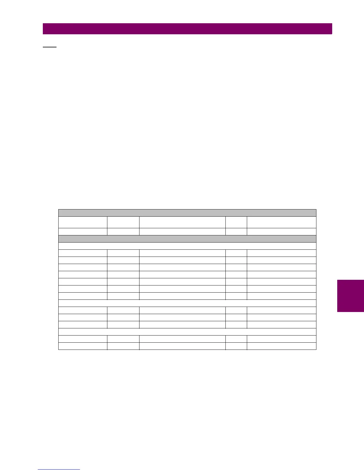
XSWI class
Attribute
Name
Attribute
Type
Explanation M/O/E Notes
XSWI Circuit switch
Data
Common Logical Node Information
Mod INC Mode M Status-only
Beh INS Behaviour M
Health INS Health M
NamPlt LPL Name plate M
Loc SPS Local operation M Local / Remote
EEHealth INS External equipment health O
OpCnt INS Operation counter M Breaker openings
Controls
Pos geDPC Switch position M Status-only
BlkOpn SPC Block opening M Status-only
BlkCls SPC Block closing M Status-only
Status information
SwTyp INS Switch Type M Fixed value = 2 (Disconnector)
SwOpCap INS Switch operating capability M Fixed value = 5