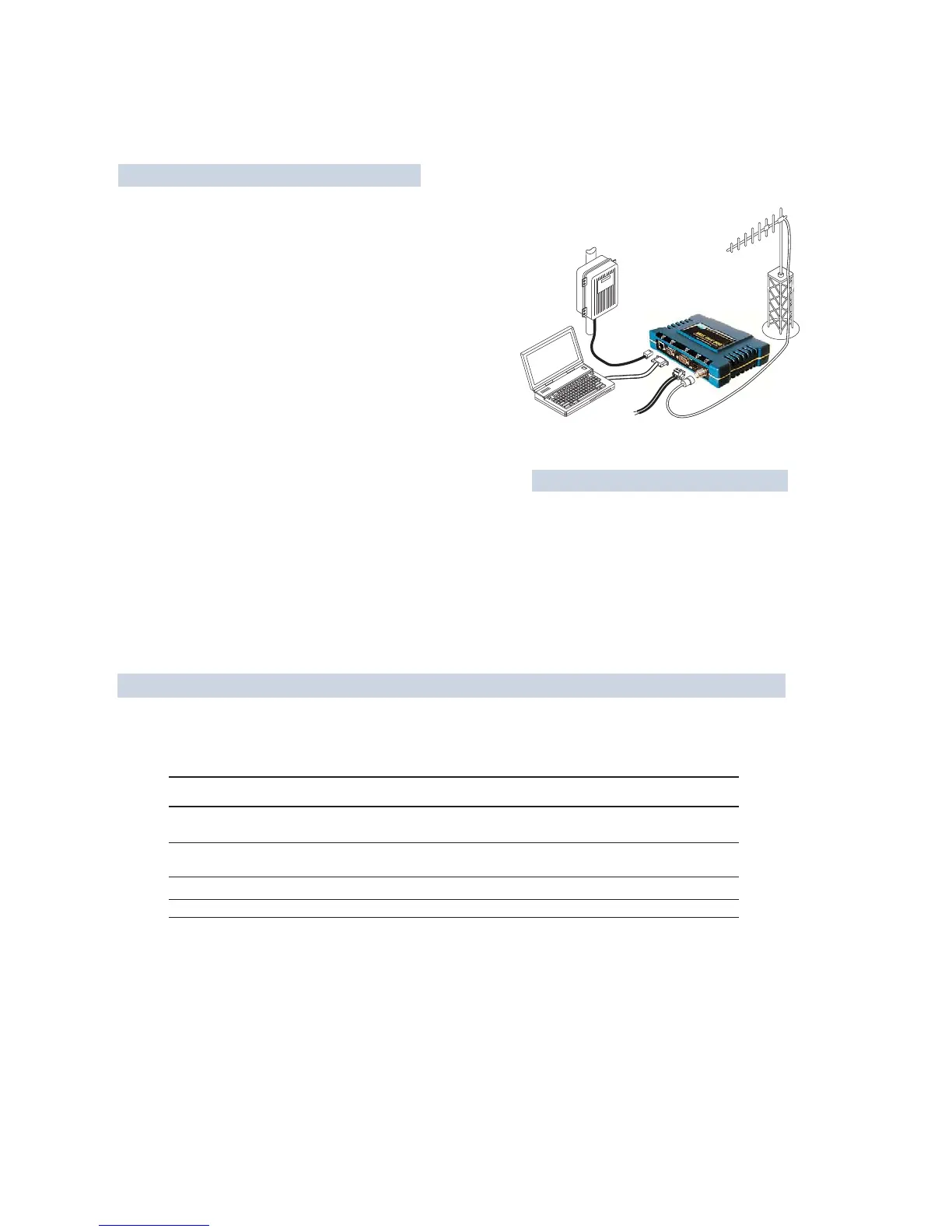
POWER SUPPLY
13.8 VDC @ 580 mA (Max.)
(10.530 Vdc)
Negative Ground Only
DATA TERMINAL
EQUIPMENT OR
LAN/WAN
COMPUTER
W/ TERMINAL
EMULATOR
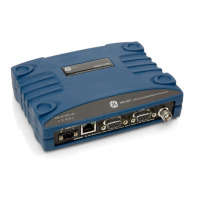
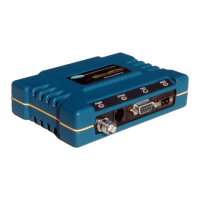
TRANSCEIVER
LOW-LOSS FEEDLINE
QUICK-ST
QUICK-ST
AR
AR
T
T
INSTRUCTIONS
INSTRUCTIONS
ANTENNA
SYSTEM
INSTALLATION SUMMARY
Step 1 Mount the Transceiver
Step 2 Install the Antenna
Step 3 Measure & Connect Primary Power (10.530 Vdc)
Step 4 Review the Tranceivers Configuration
Device ModeAccess Point, or Remote (Default)
Network NameUnique name for each radio network.
Required for Remotes to associate with Access Point.
IP AddressMust be a unique number to allow for IP access
through the Ethernet Port.
NOTE: A unique IP address is essential to access the browser-based
Management System.
RF Output PowerAdjust as necessary for regulatory compliance.
(Default = 1 Watt /+30 dBm)
PasswordUsed for remote access and some Management System
features. (Default = admin)
Step 5 Connect the Data Equipment
Connect the data equipment to data port(s):
LAN10BaseT Ethernet-compatible equipment:
Ethernet Hub (Straight-Through Cable); Ethernet Node (Crossover)
TYPICAL INSTALLATION
The Management System can be accessed through the COM1 Port using a terminal emulator. The basic items listed below, and
many other parameters and tools can be accessed through this tool. HTTP, Telnet access, and changing some parameters are
controlled by password.
BASIC CONFIGURATION DEFAULTS
COM2Serial, RS/EIA-232 compatible equipment
COM1Management System (Default); Serial (Alternate)
Step 6 Check for Normal Operation
Observe the transceiver LED status panel for the proper indications. In a normally operating system, the following LED indications
will be seen within 30 seconds of power-up:
PWRLights continuously LANOn or blinks intermittently LINK On or blinks intermittently (Remotes: if associated)
Use PING command to test basic data link integrity between Access Point and Remotes.
If the PING command is successful, connect the RTU/data equipment to the data port and verify normal operation.
If the LINK LED on Remotes is not on after 20 to 30 seconds, the unit has failed to associate with the Access Point. It may be
necessary to reposition or redirect the radios antenna for better reception/signal strength.
Check connected data equipment for normal operation
ITEM MGT SYSTEM MENU
Device Mode Network Configuration
Unit Password Device Information
Network Name Network Configuration
IP Address Network Configuration
RF Output Power Radio Configuration
VALUES/RANGE
Remote
Access Point
18 alphanumeric characters
Case-sensitive; can be mixed case
116 alphanumeric characters
Case-sensitive; can be mixed case
Contact your Network Administrator
2030 dBm @ 50W (0.11.0 Watt)
DEFAULT
Remote
admin
(lower case)
"Not Programmed"
192.168.1.1
+30 dBm (1.0 Watt)
Detailed instructions for setting transceiver parameters are contained in Section 3 of this manual.