76 iNET Series Reference Manual 05-2806A01, Rev. J
mode while others can be configured (along with the Access Point) for
UDP mode.
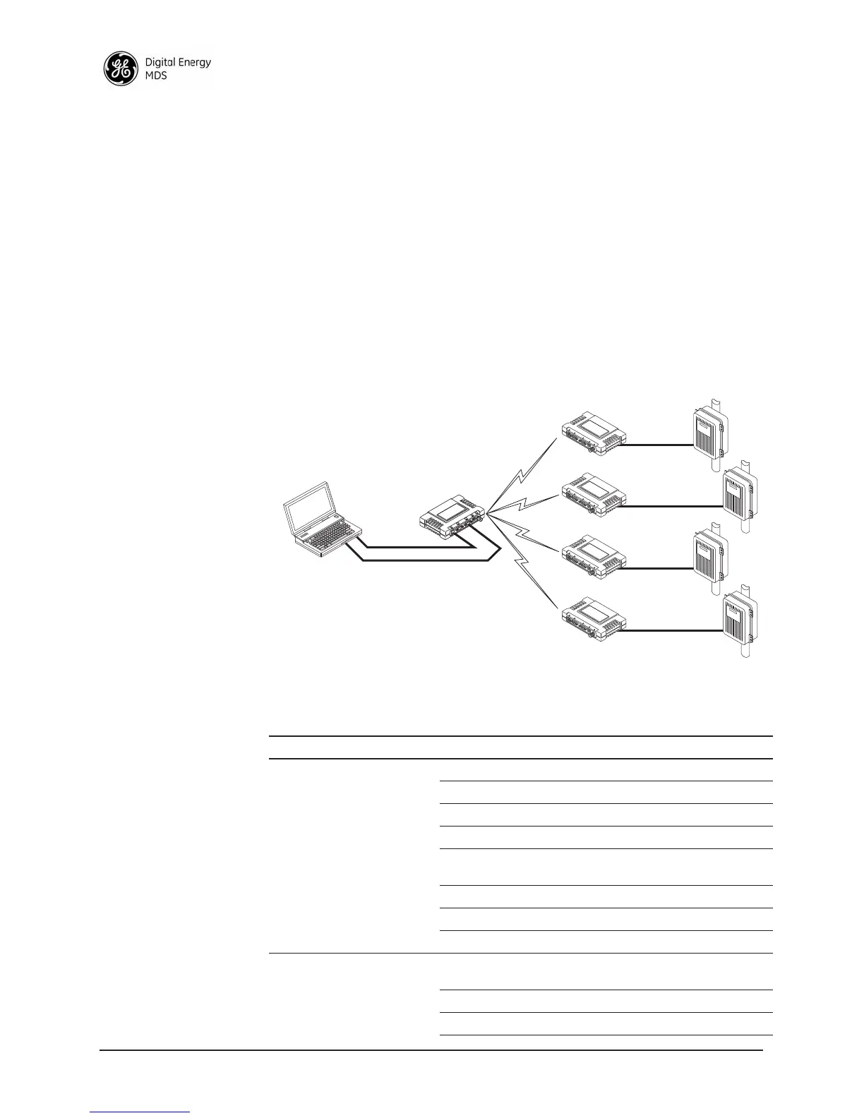
In this configuration, the Host PC can use both data paths to reach the
RTUs. This may be helpful when a mixed collection of RTUs is present
where some RTUs can operate in a broadcast form while others cannot
(see Figure 2-41 on Page 76 and Table 2-4 on Page 76).
Operation and Data Flow
• Communicate with RTU A by Telneting to Remote 1, port 30011.
• Communicate with RTU B by Telneting to Remote 2, port 30011.
• Communicate with RTUs C and D by sending and receiving data
from the Access Point’s
COM port.
• All communication paths can be used simultaneously.
Invisible place holder
Figure 2-41. Mixed-Modes Application Diagram
EIA-232
Terminal
or Computer
RTU–C
EIA-232
EIA-232
EIA-232
RTU–D
EIA-232
LA
N
COM
1
COM
2
PW
R
LIN
K
iNET 900
Remote 4
Ethernet
Crosssover
RTU–B
RTU–A
iNET 900
Access Point
LA
N
COM
1
COM
2
PW
R
LIN
K
iNET 900
Remote 1
LA
N
COM
1
COM
2
PW
R
LIN
K
iNET 900
Remote 2
LA
N
COM
1
COM
2
PW
R
LIN
K
iNET 900
Remote 3
Table 2-4. Serial Port Application Configuration
Transceiver Location Menu Item Setting
Access Point Status Enabled
Baud Rate 9,600
Flow Control Disabled
IP Protocol UDP
Send to Address A multicast IP address such as
224.254.1.1
Send to Port 30011
Receive on Port 30011
Receive on Address 0.0.0.0 (Not Used)
Remote Units 1 & 2
(COM2)
Status Enabled
Baud Rate 2,400
Flow Control Disabled
 Loading...