05-2806A01, Rev. J iNET Series Reference Manual 73
Invisible place holder
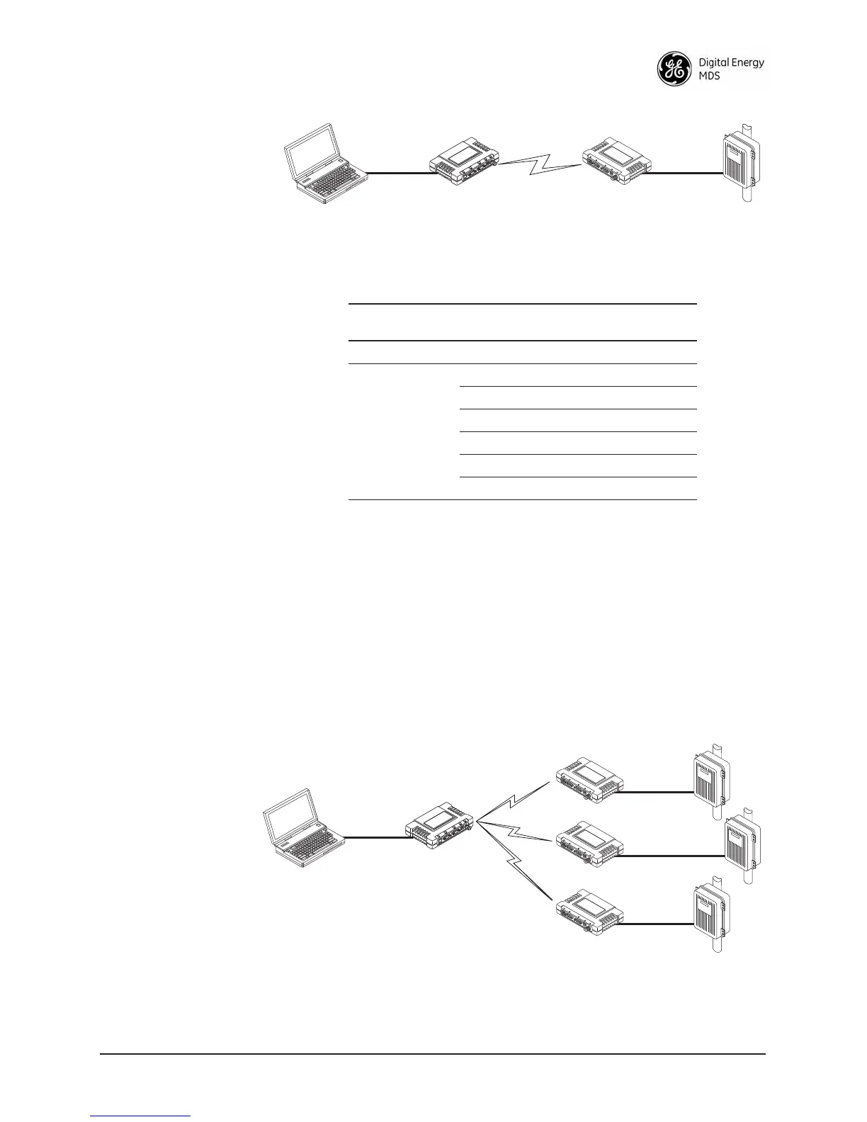
Figure 2-37. IP-to-Serial Application Diagram
2.6.7 Point-to-Multipoint IP-to-Serial Application
Example
The operation and data flow for this mode is very similar to
Point-to-Point serial-to-serial application, except that it uses multicast
addressing. The primary difference is that the PC uses UDP to commu-
nicate with all of the Remotes. Upon receiving the packet, each Remote
strips the data out of the UDP packet and sends it from its
COM port.
Likewise, data presented at any of the Remotes’
COM ports is pack-
etized, sent to the PC using the Access Point (see Figure 2-38 and
Table 2-2 on Page 73.
Invisible place holder
Figure 2-38. Point-to-Multipoint IP-to-Serial Application Diagram
Ethernet
Crosssover
RTU
EIA-232
Computer
or Network
192.168.0.10 192.168.0.1 192.168.0.2
LA
N
C
OM
1
COM
2
PW
R
LIN
K
Remote
Access Point
Table 2-1. Serial Port Application Configuration
IP-to-Serial Connection
Transceiver
Location
Menu Item Setting
Access Point None is required None is required
Remote Unit IP Address 192.168.0.2
Status Enabled
IP Protocol TCP
Baud Rate 9,600 (Example)
Flow Control None
Local IP Port 30011
192.168.0.3
192.168.0.4
EIA-232
Terminal
or Computer
RTU
RTU
RTU
EIA-232
EIA-232
EIA-232
192.168.0.10 192.168.0.1
192.168.0.2
Access Point
LA
N
COM
1
COM
2
PW
R
LIN
K
Remote
LA
N
COM
1
COM
2
PW
R
LIN
K
Remote
LA
N
COM
1
COM
2
PW
R
LIN
K
Remote
 Loading...