4. Measuring Thickness
DMS 2 Operating Manual Page 117
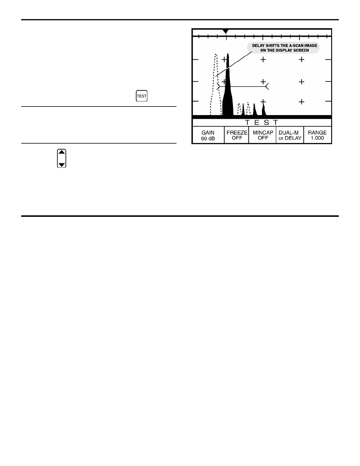
FIGURE 4-12—The A-scan on the right demonstrates
ability to move desired echoes to trigger the gate(s) for
the proper thickness measurement.
4.4.4 Positioning the A-scan with DELAY
The DELAY feature adjusts the left-to-right position of the
echo signals (returning sound pulses) in the A-scan display.
This adjustment is sometimes used to account for the
effects of signals (noise) in the initial sound pulse. This isn’t
an often-encountered problem. A typical application of the
DELAY command is shown in the two A-scans in Figure
4-12.
Step 1:
If necessary, activate the Test Menu .
NOTE: DELAY is only available in Test Mode when working
in the D-MULTI, SIP, S-FLANK, and S-PEAK measurement
modes. DELAY can be used when working in the DUAL
measurement mode but must be adjusted through the TG
Primary Menu.
Step 2:
Press below the selection titled DELAY. You’ll note
that the delay value (expressed in inches or millimeters) can be
adjusted. As the delay increases or decreases, the A-scan
display shifts to the left or right, respectively.