1. Getting Started
DMS 2 Operating Manual Page 3
Step 4: If you select the AUTO zeroing procedure, the instru-
ment will zero the probe on its own. If instead you selected
manual zeroing, zero the instrument-probe combination by
using the following procedure.
• With the probe uncoupled (not touching any material),
press
.
• Couple the probe’s measurement surface (after applying
couplant) to the ZERO BLOCK on the front of the DMS 2.
• The instrument display will indicate when the zeroing
process is complete.
NOTE: Couplant must be used between the measurement
surfaces of all probes and the material being tested. Thickness
readings can not be obtained without the use of couplant.
Step 5: Determine the material velocity by performing a one-
point calibration. Note that while the default velocity setting
represents common steel (0.2313 × 10
6
inches per second),
you must calibrate the instrument to match the specific
material that you’re inspecting. In Step 3, you selected the dual
measurement mode. Most probes will allow you to perform a
one-point calibration and operate in this mode. See Sections
3.3.1 and 3.3.4 for additional calibration options. Otherwise,
use the following procedure to calibrate your instrument.
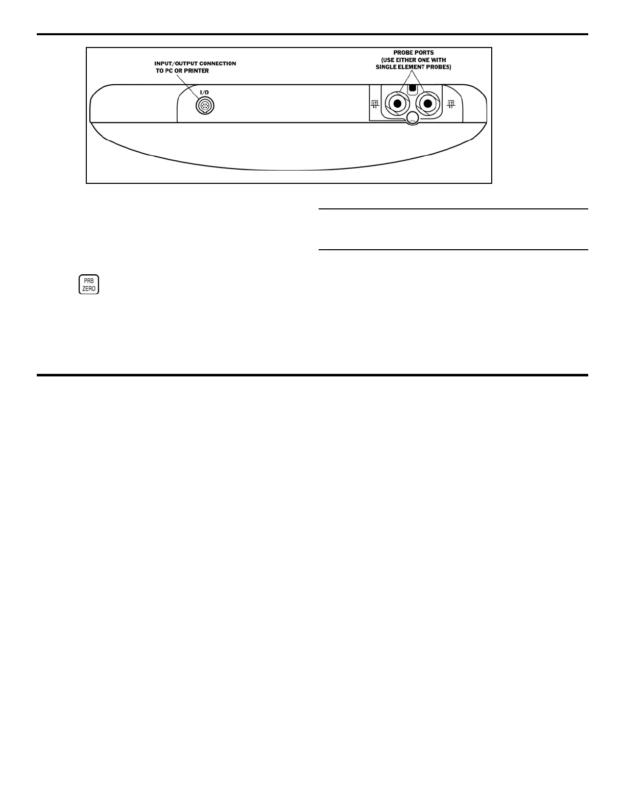
FIGURE 1-2—The instrument’s connectors are shown here.