1. Getting Started
Page 10 DMS 2 Operating Manual
Step 8:
Now that the file type and size have been specified,
the file must be named. You’ll input the FILE NAME by using
the VIRTUAL KEYBOARD. Follow this procedure to name the
file.
• To input the file name, the item FILE NAME must be
highlighted, which automatically accesses the VIRTUAL
KEYBOARD (Figure 1-7). You’ll use this keyboard to enter
file names (each up to 32 characters in length). This is also
how you’ll enter comments or notes into the DMS 2.
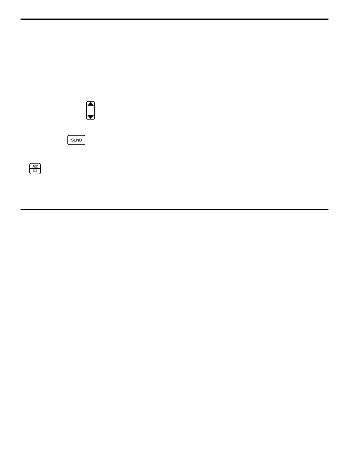
• Now, you’ll use the keyboard to assign your new file the
name TRIAL1. Use the
below each column of
characters to move the cursor from one letter to another on
the VIRTUAL KEYBOARD. When the desired letter is
selected, press
to send the letter to the FILE-
NAME LINE.
• When you’ve finished assigning the name TRIAL1, press
to return to FILE CREATION SCREEN 2 discussed in
Step 7.
• Complete the file creation process as shown in Figure
1-6. The instrument will acknowledge the new file name,
beep, and the Green LED will light if accepted.
Step 9:
At this point, you can enter an acceptable minimum
and maximum thickness for the material that you’ll be measur-
ing. For instance, if you’ve chosen a ¼-inch-thick plate to use
as a trial test piece, you might select a maximum thickness
alarm value of 0.270 inch and a minimum thickness alarm
value of 0.235 inch. (This means that visual and audible
“thickness alarms” will indicate whenever a measured thickness
falls below the minimum alarm value or above the maximum
alarm value.) Obviously, it’s up to you to determine the alarm
values you need to set to match your trial test piece. Follow this
procedure to set a minimum and maximum thickness alarm
value.
Note that if you choose not to specify any thickness
alarm at this time, you may still proceed with the rest of the
steps in this chapter.
• Follow the instructions in Figure 1-6 and specify a MIN
and MAX for the data file named TRIAL1. If you need
more information about how MIN and MAX work, refer
to Section 3.3.2.