4 PHASE CURRENT DIFFERENTIAL PROTECTION
By appropriate model selection, current differential protection can be provided for two-terminal or three-terminal
feeders. Products that have two protection communications channels fitted can be applied to the protection of
three-terminal applications.
To uniquely identify the different terminals in a scheme, a naming convention is used in the product. It uses the
terms ‘Local’ and ‘Remote’. ‘Local’ is applied to the device being described. ‘Remote’ refers to a connected device.
For a two-terminal application, the remote device is referenced in the MEASUREMENTS 3 column, etc., as ‘Remote
1’. When a third terminal is included it is referenced as ‘Remote 2’, connected to the protection communication
channel 2.
So, for a three terminal scheme, the reference terminal is the Local terminal, and it connects to Remote 1 via
communications channel 1, and to Remote 2 via communications channel 2.
At each device in the scheme, the remote current measurements received through the communications links are
processed and compared with the local signals to derive the differential current and bias current values on a per-
phase basis.
Derivation of the differential and bias currents needs to use local and remote current measurements taken at the
same point in time, but the sampling of the current signals of these devices is not directly synchronised. If not
corrected, this would cause errors. Correction is also needed to compensate for the delays involved in
communicating measurements between terminals. This compensation process is called “time alignment”. The
time-alignment process transposes remote current measurements to align them to local ones. After time
alignment of the remote current measurements to the local current measurements the differential and bias
currents can be calculated as:
● Differential current (IDiff) = vector summation of all currents entering the protected zone
● Bias current (IBias) = half the scalar sum of the currents entering the protected zone.
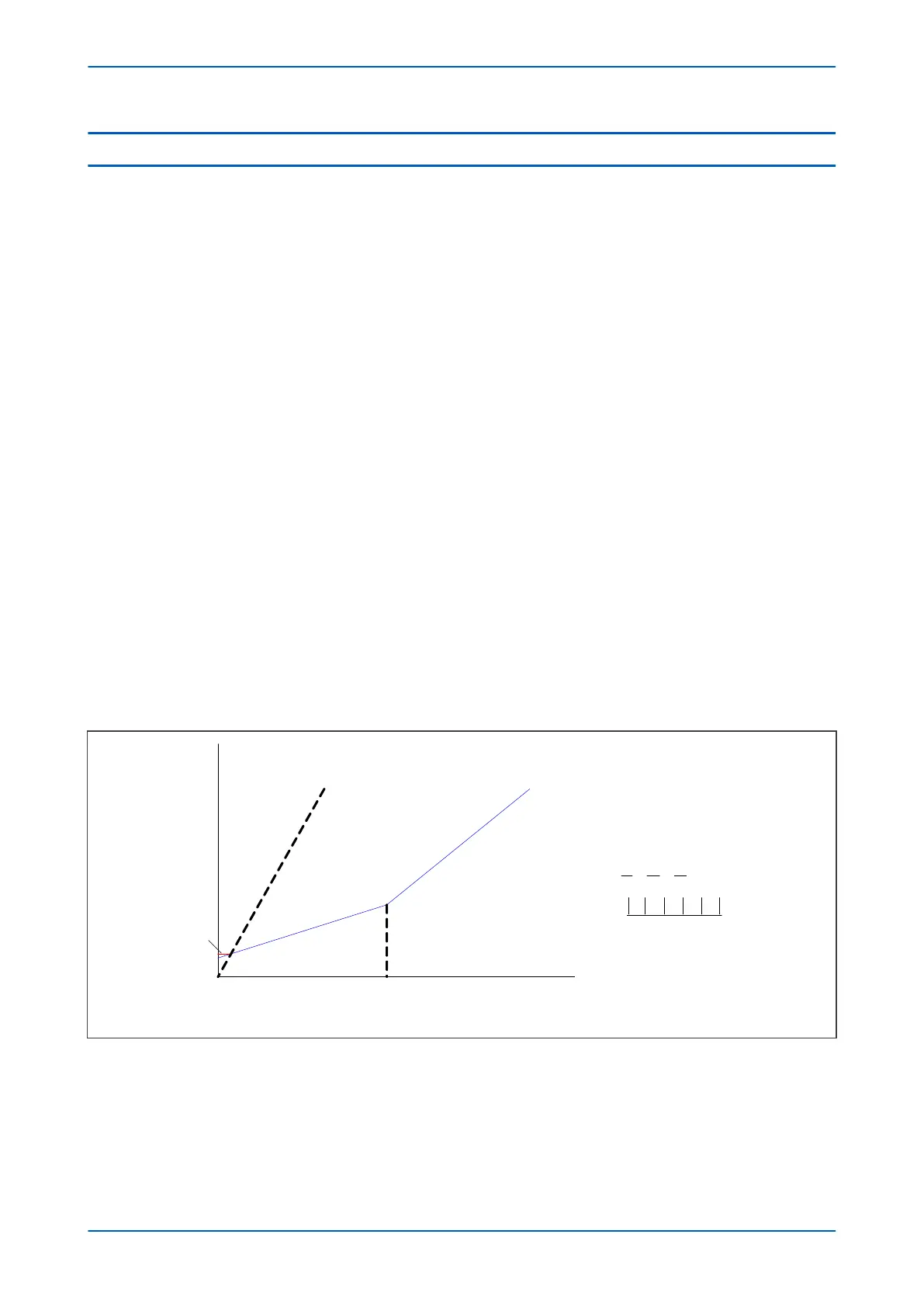
The differential and bias currents are compared against a tripping criterion which is defined by a dual-slope
characteristic as shown below. The figure shows the tripping criteria for protection of a three-terminal feeder, but
the principle is similar for a two-terminal feeder.
V02605
Phase IS1
Phase IS2
Restrain
Operate
Phase K1 Slope
Phase K2 slope
For a three-terminal feeder where:
I
1
= I
local
I
2
= I
remote1
I
3
= I
remote2
I
diff min
200% slope
I
diff
I
bias
Figure 36: Dual slope current differential bias characteristic
P543i/P545i Chapter 6 - Current Differential Protection
P54x1i-TM-EN-1 105

 Loading...


