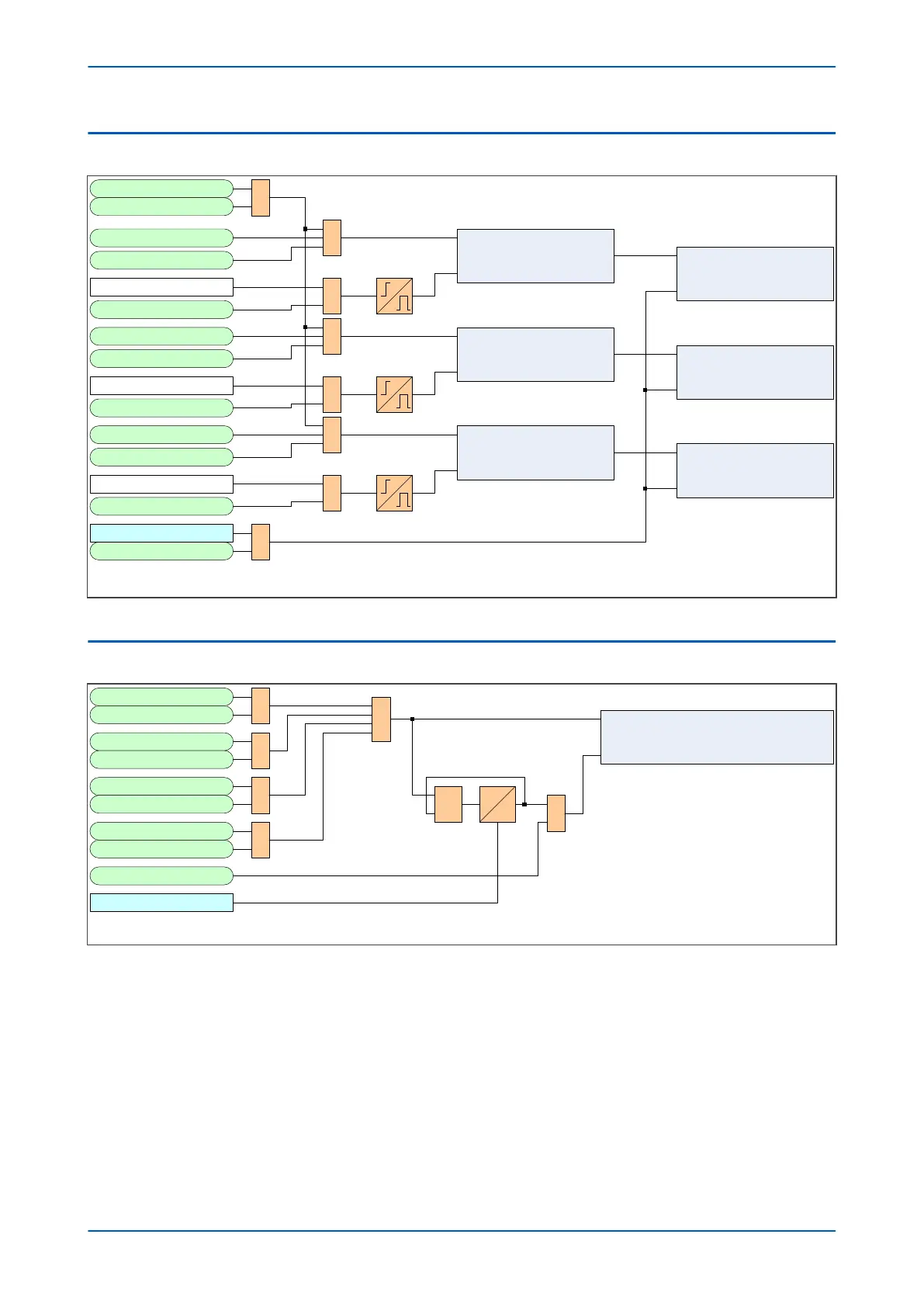
5.3 CB OPERATING TIME ACCUMULATOR
V01274
CB operating time phase A
Start
Stop
Trip 3ph
1
External Trip3ph
Trip Output A
External Trip A
Trip Output B 1
External Trip B
Note : CB operating time not accumulated when device is in test mode
Pole Dead A
CB operating time phase B
Start
Stop
1
1
Pole Dead B
1
Trip Output C 1
External Trip C
CB operating time phase C
Start
Stop
Pole Dead C
1
1
Reset CB Data
Reset CB Data
CBOpTimePhA Counter
Increment
Reset
CBOpTimePhB Counter
Increment
Reset
CBOpTimePhB Counter
Increment
Reset
IA < fixed threshold
IB < fixed threshold
IC < fixed threshold
Figure 243: Operating Time Accumulator
5.4
EXCESSIVE FAULT FREQUENCY COUNTER
V01278
Trip 3ph
External Trip3ph
Trip Output A
External Trip A
Trip Output B
External Trip B
Trip Output C
External Trip C
1
1
1
1
Excessive Fault Frequency Counter
Increment
Reset
1
R
Q
S
0
t
1
Lockout Alarm
Fault Freq Time
Figure 244: Excessive Fault Frequency logic diagram
Chapter 17 - Monitoring and Control P543i/P545i
438 P54x1i-TM-EN-1

 Loading...


