S2 = Iph
Ð
σ
where: Z
replica
is the replica forward reach
The impedance below the Impedance Reach line is detected when the angle between the signals is less than 0°:
For products that have mutual compensation, if the mutual compensation is applied, then
Z
replica
=Z(1+k
ZN
.IN/Iph+k
ZM
.I
M
/Iph).
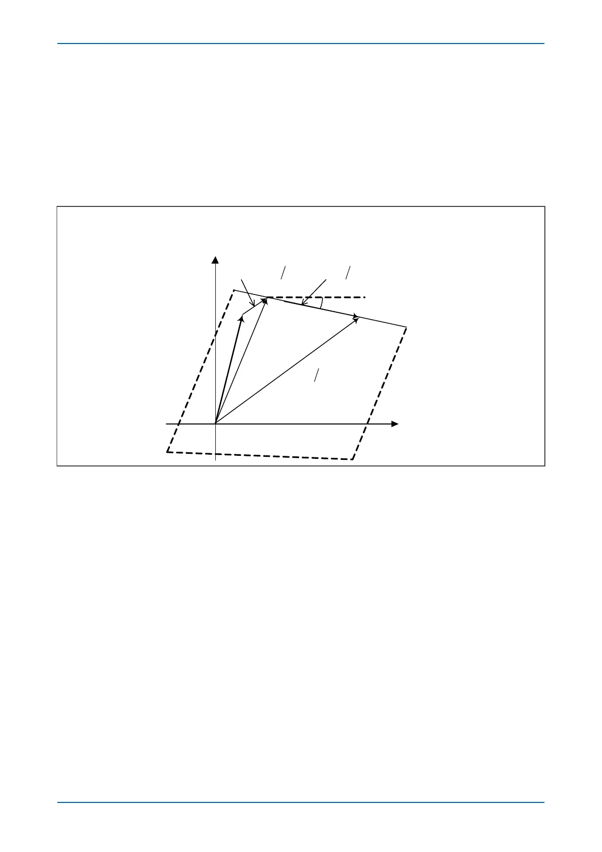
The following figure shows the Z
LP
-plane representation of the characteristic:
Figure 66: Impedance Reach line in Z
LP
plane
The Impedance Reach line tilting angle in the Z
LP
plane is fixed at σ (Zx Tilt Top Line setting).
The Impedance Reach line tilting angle in the Z1 plane is defined as follows:
Tilt angle =
Ð
(Iph/I) + σ =
Ð
(Iph/(Iph + kZ
N
.IN)) + σ
If the healthy phase currents are much less than the current of the faulty phase, then IN ≈ Iph. The tilting angle in
this case is fixed at the following value:
Tilt angle =
Ð
((1/(1 + kZN)) + σ
For products that have mutual compensation, if the mutual compensation is enabled, the tilting angle is:
Tilt angle =
Ð
(Iph/(Iph + k
ZN
.IN+ k
ZM
.I
M
)) + σ
The replica reach Z
replica
depends on the ratio of IN/Iph. If IN ≈ Iph (and if mutual compensation is not applied)
then:
Z
replica
=Z (1 + k
ZN
)
So the characteristic is static.
The general characteristic in the Z
LP
plane is shown in the following figure:
P543i/P545i Chapter 7 - Distance Protection
P54x1i-TM-EN-1 157

 Loading...


