GE Power Management
MM2 Motor Manager 2 6-23
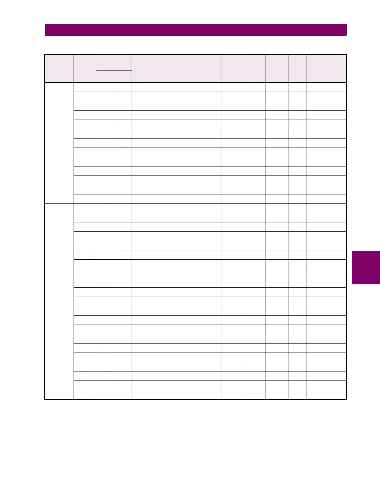
6 COMMUNICATIONS 6.5 MEMORY MAP
6
TIMERS 30113 112 0070 Undervoltage Restart Timer --- --- 0.1 x s F1 N/A
30114 113 0071 AUX1 Post Contactor A Delay Timer --- --- s F1 N/A
30115 114 0072 Transfer Timer --- --- 0.5 x s F1 N/A
30116 115 0073 First Stage Timer --- --- 0.5 x s F1 N/A
30117 116 0074 Second Stage Timer --- --- 0.5 x s F1 N/A
30118 117 0075 Start Inhibit Timer --- --- s F1 N/A
30119 118 0076 AUX2 Post Contactor A Delay Timer --- --- s F1 N/A
30120 119 0077 AUX 1+2 Pre Con. A Delay Timer --- --- s F1 N/A
30121 120 0078 AUX1 Pre Con A Post Start Dly Timer --- --- s F1 N/A
30122 121 0079 AUX2 Pre Con A Post Start Dly Timer --- --- s F1 N/A
30123 122 007A ...Reserved... ... ... ... ... ...
↓↓↓ ↓ ↓ ↓ ↓↓ ↓
30128 127 007F ...Reserved... ... ... ... ... ...
DEBUG
DATA
30129 128 0080 ADC Reference --- --- --- F1 N/A
30130 129 0081 Thermistor Reading --- --- kOhms F1 N/A
30131 130 0082 Power Loss Fine Time --- --- 10 ms F1 N/A
30132 131 0083 Power Loss Coarse Time --- --- 0.1 min F1 N/A
30133 132 0084 Current key press --- --- --- F24 N/A
30134 133 0085 Internal Fault Error Code --- --- --- --- N/A
30135 134 0086 Phase A Current (fast update) --- --- ** F1 N/A
30136 135 0087 Phase B Current (fast update) --- --- ** F1 N/A
30137 136 0088 Phase C Current (fast update) --- --- ** F1 N/A
30138 137 0089 Ground Current (fast update) --- --- 0.1 x A F1 N/A
30139 138 008A Voltage (fast update) --- --- V F1 N/A
30140 139 008B Current Display Line --- --- --- F1 N/A
30141 140 008C Current Display Mode --- --- --- F1 N/A
30142 141 008D ...Reserved... ... ... ... ... ...
30143 142 008E ...Reserved... ... ... ... ... ...
30144 143 008F ...Reserved... ... ... ... ... ...
30145 144 0090 Message Buffer characters 1 and 2 --- --- ASCII F10 N/A
30146 145 0091 Message Buffer characters 3 and 4 --- --- ASCII F10 N/A
30147 146 0092 Message Buffer characters 5 and 6 --- --- ASCII F10 N/A
30148 147 0093 Message Buffer characters 7 and 8 --- --- ASCII F10 N/A
30149 148 0094 Message Buffer characters 9 and 10 --- --- ASCII F10 N/A
Table 6–12: MODBUS MEMORY MAP (Sheet 4 of 21)
GROUP MOD-
ICON
REGISTER
ADDRESS DESCRIPTION REGISTE
R VALUE
RANGE
STEP
VALUE
UNITS
AND
SCALE
FOR-
MAT
FACTORY
DEFAULT
VALUE
(CONVERTED)
DEC HEX
Notes: * – Maximum setpoint value and 65535 represent OFF
** – 1/Phase Current Scale Factor x A
*** – 101 represents unlimited
† – Minimum setpoint value represents OFF
~* – 0.1 x A when Hi resolution mode is disabled; 0.01 x A when enabled

 Loading...


