6-24 MM2 Motor Manager 2
GE Power Management
6.5 MEMORY MAP 6 COMMUNICATIONS
6
DEBUG
DATA
con’t
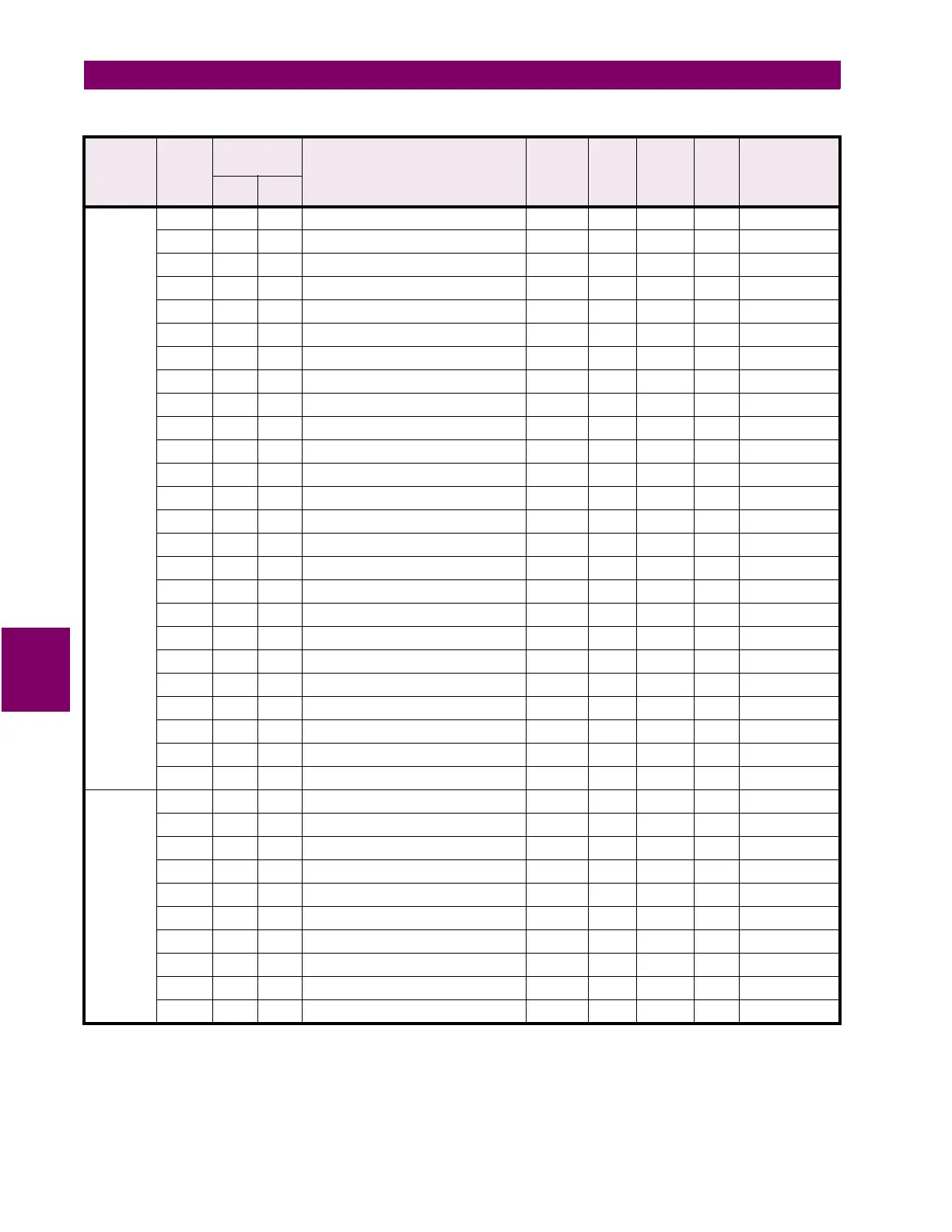
30150 149 0095 Msg. Buffer characters 11 and 12 --- --- ASCII F10 N/A
30151 150 0096 Msg. Buffer characters 13 and 14 --- --- ASCII F10 N/A
30152 151 0097 Msg. Buffer characters 15 and 16 --- --- ASCII F10 N/A
30153 152 0098 Msg. Buffer characters 17 and 18 --- --- ASCII F10 N/A
30154 153 0099 Msg. Buffer characters 19 and 20 --- --- ASCII F10 N/A
30155 154 009A Msg. Buffer characters 21 and 22 --- --- ASCII F10 N/A
30156 155 009B Msg. Buffer characters 23 and 24 --- --- ASCII F10 N/A
30157 156 009C Msg. Buffer characters 25 and 26 --- --- ASCII F10 N/A
30158 157 009D Msg. Buffer characters 27 and 28 --- --- ASCII F10 N/A
30159 158 009E Msg. Buffer characters 29 and 30 --- --- ASCII F10 N/A
30160 159 009F Msg. Buffer characters 31 and 32 --- --- ASCII F10 N/A
30161 160 00A0 Msg. Buffer characters 33 and 34 --- --- ASCII F10 N/A
30162 161 00A1 Msg. Buffer characters 35 and 36 --- --- ASCII F10 N/A
30163 162 00A2 Msg. Buffer characters 37 and 38 --- --- ASCII F10 N/A
30164 163 00A3 Msg. Buffer characters 39 and 40 --- --- ASCII F10 N/A
30165 164 00A4 ...Reserved... ... ... ... ... ...
↓↓↓ ↓ ↓ ↓ ↓↓ ↓
30176 175 00AF ...Reserved... ... ... ... ... ...
30177 176 00B0 Second Mod File Number --- --- --- F1 N/A
30178 177 00B1 Third Mod File Number --- --- --- F1 N/A
30179 178 00B2 Fourth Mod File Number --- --- --- F1 N/A
30180 179 00B3 Fifth Mod File Number --- --- --- F1 N/A
30181 180 00B4 ...Reserved... ... ... ... ... ...
↓↓↓ ↓ ↓ ↓ ↓↓ ↓
30256 255 00FF ...Reserved... ... ... ... ... ...
USER
DEF.
DATA
30257 256 0100 User Definable Data 0000
30258 257 0101 User Definable Data 0001
30259 258 0102 User Definable Data 0002
30260 259 0103 User Definable Data 0003
30261 260 0104 User Definable Data 0004
30262 261 0105 User Definable Data 0005
30263 262 0106 User Definable Data 0006
30264 263 0107 User Definable Data 0007
30265 264 0108 User Definable Data 0008
30266 265 0109 User Definable Data 0009
Table 6–12: MODBUS MEMORY MAP (Sheet 5 of 21)
GROUP MOD-
ICON
REGISTER
ADDRESS DESCRIPTION REGISTE
R VALUE
RANGE
STEP
VALUE
UNITS
AND
SCALE
FOR-
MAT
FACTORY
DEFAULT
VALUE
(CONVERTED)
DEC HEX
Notes: * – Maximum setpoint value and 65535 represent OFF
** – 1/Phase Current Scale Factor x A
*** – 101 represents unlimited
† – Minimum setpoint value represents OFF
~* – 0.1 x A when Hi resolution mode is disabled; 0.01 x A when enabled

 Loading...


