GE Power Management
MM2 Motor Manager 2 6-35
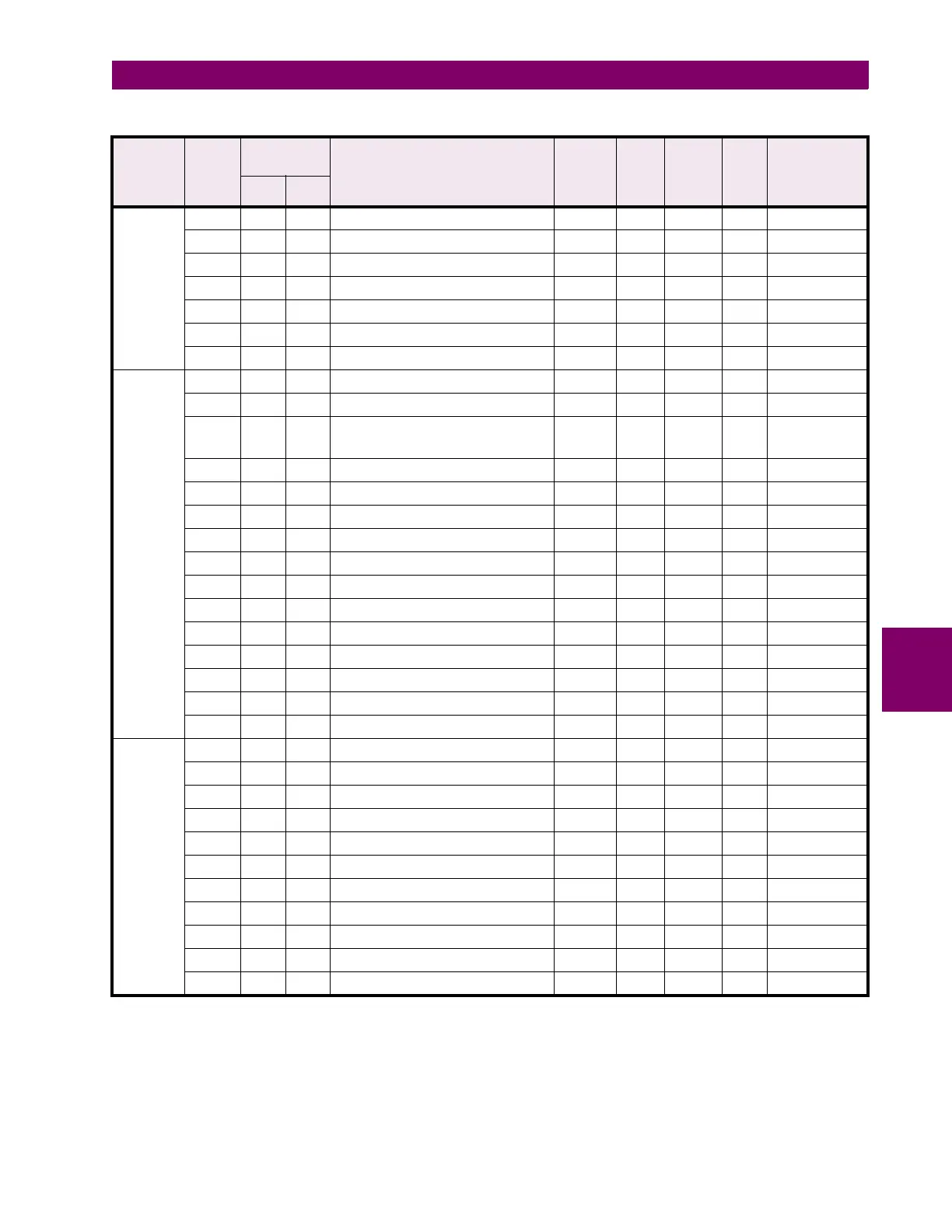
6 COMMUNICATIONS 6.5 MEMORY MAP
6
FLASH
MESSAGE
continued
44441 4440 1158 Flash message characters 33 and 34 32-255 1 ASCII F10 " "
44442 4441 1159 Flash message characters 35 and 36 32-255 1 ASCII F10 " "
44443 4442 115A Flash message characters 37 and 38 32-255 1 ASCII F10 " "
44444 4443 115B Flash message characters 39 and 40 32-255 1 ASCII F10 " "
44445 4444 115C ...Reserved... ... ... ... ... ...
↓↓↓ ↓ ↓ ↓ ↓↓ ↓
44448 4447 115F ...Reserved... ... ... ... ... ...
COM-
MANDS
44449 4448 1160 Command Function Code 5 --- --- F1 5
44450 4449 1161 Command Operation Code 1-32 1 --- F22 0
44451 4450 1162 Command Data 1 0-65535 1 ---
F1/F23/
F26
0
44452 4451 1163 Command Data 2 0-65535 1 --- F1 0
44453 4452 1164 Command Data 3 0-65535 1 --- F1 0
44454 4453 1165 Command Data 4 0-65535 1 --- F1 0
44455 4454 1166 Command Data 5 0-65535 1 --- F1 0
44456 4455 1167 Command Data 6 0-65535 1 --- F1 0
44457 4456 1168 Command Data 7 0-65535 1 --- F1 0
44458 4457 1169 Command Data 8 0-65535 1 --- F1 0
44459 4458 116A Command Data 9 0-65535 1 --- F1 0
44460 4459 116B Command Data 10 0-65535 1 --- F1 0
44461 4460 116C ...Reserved... ... ... ... ... ...
↓↓↓ ↓ ↓ ↓ ↓↓ ↓
44464 4463 116F ...Reserved... ... ... ... ... ...
UNDER/
OVER
VOLTAGE
PROTEC-
TION
44465 4464 1170 Undervoltage Alarm Level 0-691 1 V F1 * 691 = 0FF
44466 4465 1171 Undervoltage Alarm Delay 1-60 1 s F1 10
44467 4466 1172 Undervoltage Trip Level 0-691 1 V F1 * 691 = 0FF
44468 4467 1173 Undervoltage Trip Delay 1-60 1 s F1 10
44469 4468 1174 Overvoltage Alarm Level 0-691 1 V F1 * 691 = 0FF
44470 4469 1175 Overvoltage Alarm Delay 1-60 1 s F1 10
44471 4470 1176 Overvoltage Trip Level 0-691 1 V F1 * 691 = 0FF
44472 4471 1177 Overvoltage Trip Delay 1-60 1 s F1 10
44473 4472 1178 ...Reserved... ... ... ... ... ...
↓↓↓ ↓ ↓ ↓ ↓↓ ↓
44480 4479 117F ...Reserved... ... ... ... ... ...
Table 6–12: MODBUS MEMORY MAP (Sheet 16 of 21)
GROUP MOD-
ICON
REGISTER
ADDRESS DESCRIPTION REGISTE
R VALUE
RANGE
STEP
VALUE
UNITS
AND
SCALE
FOR-
MAT
FACTORY
DEFAULT
VALUE
(CONVERTED)
DEC HEX
Notes: * – Maximum setpoint value and 65535 represent OFF
** – 1/Phase Current Scale Factor x A
*** – 101 represents unlimited
† – Minimum setpoint value represents OFF
~* – 0.1 x A when Hi resolution mode is disabled; 0.01 x A when enabled

 Loading...


